Update bulletin January 2004
Sources of parts and tools
Magnets for the USA version of the plans (2" x 1" x 1/2") only $6.75 each for 25 pieces
drawknife source A
drawknife source B
resin in the USA
Two problems have arisen with a small number
of machines built to the design as published.
The alternator is very efficient compared to
previous homebrew designs. This means that it's rpm does not vary so widely
as others do between cut in speed and full power. The speed remains rather
constant. But the speed of the blades needs to vary much more widely if
they are to work aerodynamically at their best. The result is that the
alternator runs too slow for the blades at full power or too fast for the
blades at cut-in, or both.
I instinctively prefer to optimise performance
in low winds. I therefore opted for low speed when I designed the alternators.
They do sometimes stall the blades as the wind increases. This means that
the windmill works well in low winds, but as the wind increases, the current
does not rise beyond a certain point. The machine is slow and quiet, but
the output is seriously disappointing. (It levels off at about 120-150
watts.) This occurs mostly in the case of 24 or 48 volt systems with short,
thick cables, when the battery voltage is low. The problem is less likely
to arise in the case of the US 12 volt model.
There are several types of solution.
1. One is to increase the alternator rpm. This can be done by increasing the space between magnet rotors so that there is a larger gap each side of the stator. Or wind the stator with fewer turns in each coil. This prevents stall but it will also mean a higher cut in rpm, resulting in some slight loss of performance in low winds (around 3 m/s or 7 mph). These are both good, simple solutions.
2. You can also increase the range of speed of the alternator, by increase the circuit resistance. Using a longer or thinner cable is one way to do this. This allows you to put the machine further away without excessive cost. Choose cables sizes (on page 40) for 30% loss at 500 watts. Or use a resistor (12V=0.15ohms, 24 volts=0.6 ohms, 48 volts = 2.4 ohms). These values are only suggestions. The resistor needs to be able to handle 500 watts when the machine output is 700 watts. Maybe you could use it to heat water? It may seems crazy to burn off power, but it improves the blade efficiency over the whole range, has very little impact on efficiency in low winds and is a relatively simple solution too.
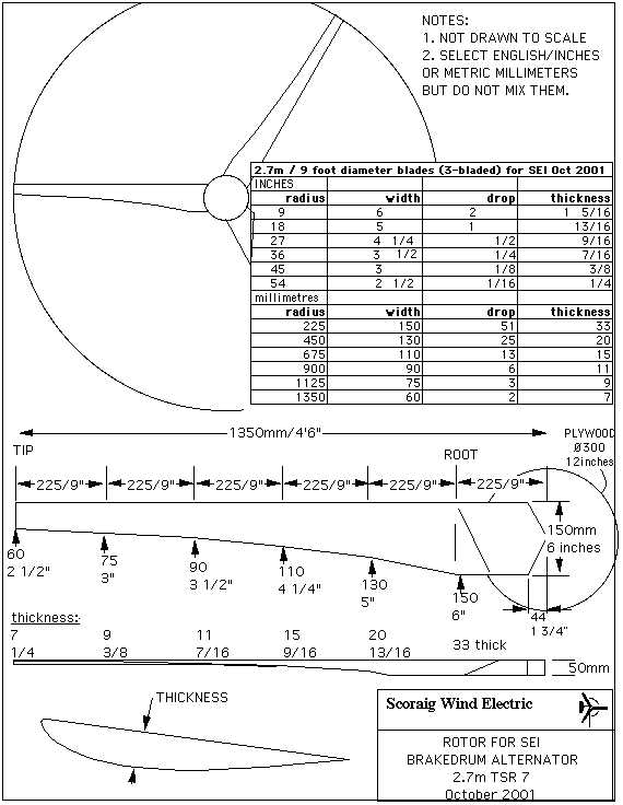
3. Or you can put a larger diameter set of blades on the machine say 2.7 metres/9 feet. Scale up all the dimensions (length, width, drop and thickness). Or use the dimensions lower down this page. I only recommend going up to 9 feet if you seriously want a larger wind turbine. I have tried it and it seems to work well. But there may be extra loads on everything due to the larger rotor.
4. Finally you can use some sort of electronic
voltage converter between the input from the windmill and the battery.
This is only for electronic wizards. this promises to be the only 'real'
solution but it is still under development and I worry about the consequences
for cost and reliability.
In reply, "Nando" <[email protected]> writes:
The solution is to allow the mill to generate the highest possible voltageI am open to all suggestions. I have several people helping me with ideas for this, but thus far I have not seen a nice simple solution with good reliability.
and do a DC/DC conversion at the battery with MPPT, this way maximum power
is transferred without the need to add un-necessary loses, reducing the
capacity and/or efficiency of the wind mill, of course you may need to have
a dump load if the mill is not self RPM regulated.The ideal set up is to have a mill that produces a voltage around 2 times
the battery voltage at the lowest wind regime and a DC/DC with MPPT
converter capable of accepting the voltages from low to highest wind regimes
to attain around 92 to 97 % conversion efficiency, MUCH greater than the 70
% you are suggesting with the changes.>this promises to be the only 'real' solution but it is still under
>development.Are you doing the development ?. I could assist in this matter, now that I
will have more time available..
===============
Use these coil turns specifications:
| Voltage | Old | New | Wire |
| model | number | number | size |
| 12V mm | 90 TURNS | 70 TURNS | 1.6mm |
| 24V mm | 180 | 125 | 1.18mm |
| 48V mm | 360 | 250 | 0.8mm |
| 12V US | 80 | 80 | #15 (or 2 x #18)
AMERICAN WIRE GAUGE |
| 24V US | 160 | 150 | #18 AWG |
| 48V US | 320 | 290 | #21 (or 2 x #24) AWG |
If it is too late, then you can use the stator you have already made, but increase the clearance between rotor and stator a few mm each side, to avoid stalling. I suggest about 4-6mm clearance for the 48 volt metric version.
Choose cables sizes (on page 40) for 30% loss at 500 watts. You can try using thicker cables if you like but check to see if it causes reduced output.
================
I have one of these machines sited on the north
side of Scoraig where the wind comes down the hill in sudden squalls and
hits with a punch. The machine has a tendency to smash its blade tips against
the tower in these weather conditions. I believe this happens because of
the sudden yawing of the rotor. Gyroscopic forces push the blades backwards.
I have also recently had reports of another machine in Ireland with this
problem.
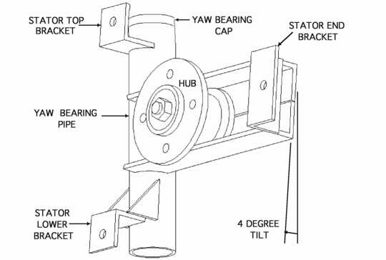
The first solution is fairly simple. I would
normally tilt the axis of the alternator slightly so as to increase the
tower clearance of the blade tips. The reason why I did not design the
machine with a tilt in this case was to try to make the welding simpler.
I regret that now. On good sites with clean winds the machine works without
problems, but I'd rather it were foolproof and so I'll be adapting the
drawings to include a tilt of about 4 degrees in future editions.
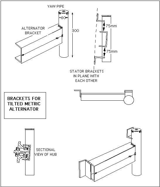
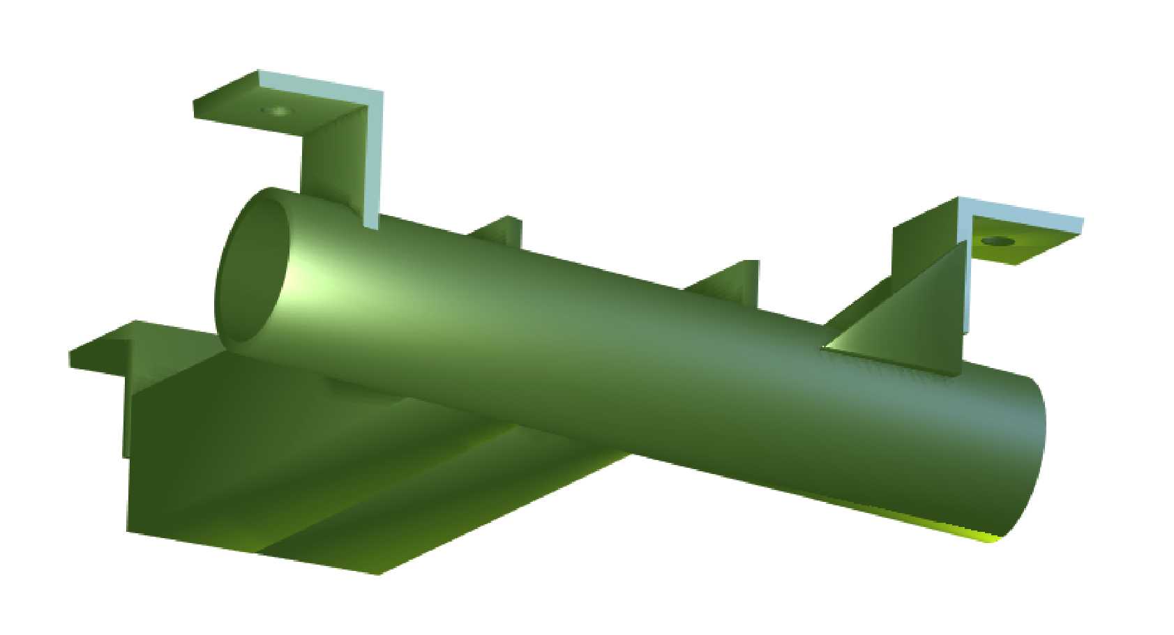
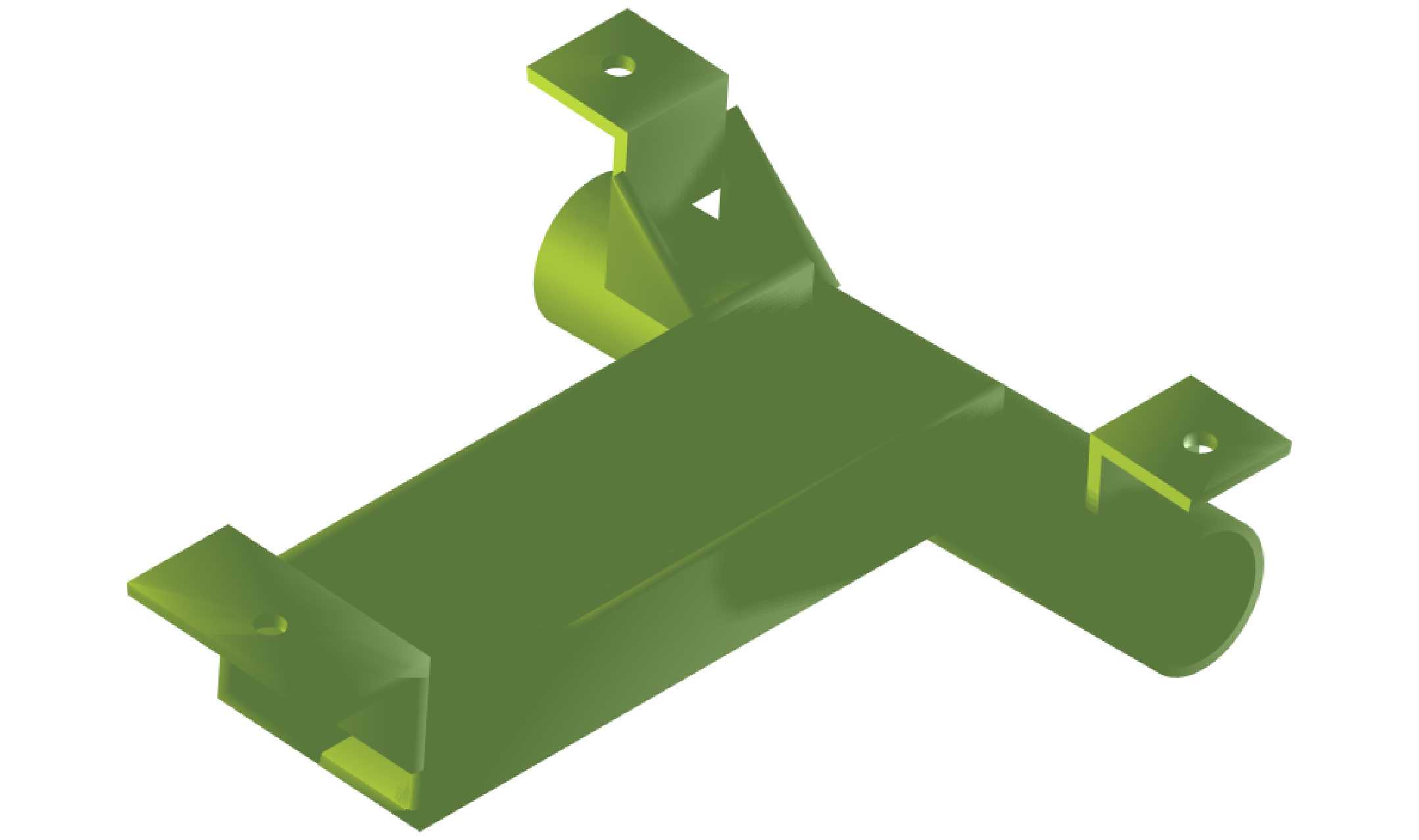
Here are some drawings.
There is another solution though...
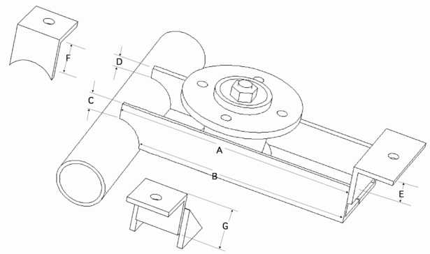
| Frame dimensions | UK version | USA version |
| A length of angle | 293 mm | 11 1/2" |
| B length inside notch | 263 mm | 10 3/8" |
| C width of end of lower steel angle piece | C = 98 - X
= 20 mm |
C = 3 7/8" - X
=1 1/4" |
| D width of end of upper steel angle piece | D = 91 - X
= 13 mm |
D = 3 5/8" - X
= 1" |
| E upstand of end stator bracket | 26 mm | 1" |
| F upstand of top stator bracket from pipe | 36 mm | 2 3/8" |
| G upstand of lower stator bracket | 51 mm | 2" |
I am indebted to Tod Hanley
for the following alternative solution . It's so simple I wish I
had thought of it. The gyro forces are probably only a problem when
the machine is yawing away from the wind (spinning fast and kicking away).
The direction of gyroscopic deflection depends on the rotation of the blades
and the direction of yaw.
There you go :-)
Hi Hugh,I have a bit of a suggestion, may mess things up.
I am not sure, but it looks like you might want to solve the blade tip
whacking by reversing the rotation, such that as the machine furls the
clearance increases. I hate all of the right hand rule stuff, so I take
a bike wheel hold it by the quick release, then spin it in one direction
while "furling" it to the side. If it whacks you in the knees, try
spinning it the other direction. If it puts tread marks on your
forehead, as you "furl" it that's probably the best rotation.
Best regards,
Tod
More ideas will appear on this page as they come...
Back to my home page