"How to Build a wind turbine" course in France 2007

En Francais

Chez KRUG S.A.R.L.

Chemin de Magrignac
31290 Avignonet-Lauragais - France
Tel +33 (0)5 34 66 79 06
Mob +33 (0)6 99 09 09 12
Fax +33 (0)5 61 83 14 21

6 - 11 August 2007

The main language spoken was French.  I can now speak enough to explain a few things, but I also spoke in English and Jay or Pierre translated for me.

We  got together and built two turbines:
In the picture from left to right - Olivier Krug, head of Krug SARL who conceived the idea of the course.  Jay Hudnall who made it happen.  Participants Alain, Pierre, Guy, Thomas, Guy, Thomas, Bertrand, Lawrence, Alexander, Yvan and Sylvain.

Main headings below are:

Krug SARL is situated among ten lovely big 800 kW Nordex turbines each about 50 metre diameter on the road from Toulouse to Carcassonne.


Thanks to Jay for organising everything and feeding us and for connecting our turbine to the grid with a 'Windy Boy' inverter.


Blades for the 4 metre machine

radius chord drop thick
250 205 52 35
500 205 42 32
750 187.5 32 25
1000 170 22 21
1250 152.5 12 18
1500 135 9 16
1750 117.5 6 13
2000 100 3 11

Here Alain and Pierre set the 'drop' measurement using a vertical spirit level as a reference, because the wood was very slightly warped.

Pierre works on the thickness.

The finished blades fitted in the workshop for balancing.


Hub and steel parts for the 4 metre diameter turbine

The hub came from a Renault Master van, or possibly a Fiat of the same size.  It is just like the hubs we used in previous courses here in France.  It has a nice big flange at the back of the shaft for mounting on a flat surface, and 4 @ 12mm holes in the corners.


Alex holds the alternator frame.  I have a new approach to the stator mounts which is to make a very simple frame of steel angle at the start and then to add this to the yaw bearing afterwards.  Extra strengthening is easy to add once the basic shape has been achieved.


Above you can see the pieces used to fit the frame to the yaw tube.  Only one curved cut is required for the yaw bearing fabrication in this case.  The plate on the top of the yaw tube is rectangular.


I also decided on a simpler system for the tail hinge, using the same size pipes as the yaw bearing to form a strong, weatherproof hinge that can be put together with relative ease.  Above you can see the frame supported at an angle to the bench so the inner part of the tail hinge can be fitted to it lying horizontally.  The inner pipe here held by Laurence has external/outer diameter 76mm. 
73mm outer diameter could also be used.  2 1/2 inch nominal bore pipe has outer diameter 73mm.


We used a measurement of 120 mm to set the 20 degree angle of the tail hinge.  More detailed shots of the structure of the turbine can be seen in the assembly pictures later.  It's a luxury to work with French tape measures that have only millimetres, and no inches on them at all.


The coils and the stator casting


I have started to use a much simpler shape of coil winder which has two disks of ply outside the inner former.  We wrap the top of each coil together easily with a piece of wire before removing it from the winder, and then apply the insulating tape around the side 'legs' of the coils as before.  It is easier and quicker to do it like this.


Guy, Sylvain and Thomas admire the stator and start to trim the excess resin while it is still a little soft.

The coils in the Stator

No. of coils:         12
Turns per coil:        400
Wire size :    0.71 diameter exterior
Weight per coil:    300 grams
Coil connections :Series/ star (wye)

Resistance per coil    approx. 4 ohms
Resistance of stator    30 ohms

Predicted output
200 volts at 103 rpm
1700 watts at 400 volts at
300 rpm with 75% efficiency.


The stator casting above has four corners, but the shape is a little more compact than the simpler square shape I have used for machines this size in recent years.  This makes the mounting more compact and generally looks a little neater and tighter.


The stator came out nicely.  Alain holds it up for inspection.  Behind him you can see a 6kW Proventhat burned out.

In this case it is important to know which magnet is which, and thus to make sure that the two rotors will attract each other when assembled.  We used an index mark to keep track of this, with our five mounting holes.  We only used 3 holes for the moulds and templates.


Assembly and erection of the turbine


Jay fits the stator, held by Alex.  It drops into place nicely.  The first magnet rotor has already been fitted onto the 5 M14 studs.  We used 'bright zinc plated' studs (ordinary steel) instead of stainless studs on this turbine.  We used M12 for the stator mounts.


We took great care with fitting the second rotor, using 3 M14 jacking screws to prevent crushed fingers.  But we did then find out that the spacing washers were different thicknesses, and we took a while to arrive at the right spacing, and to get the magnet rotors running true.


In the end we were a bit horrified to find that one coil had been reversed during the casting process.  We found this due to imbalance in the output voltages, and we located the coil by connecting the stator to a 12 volt battery.  The DC current makes each coil into a magnet, and the rogue coil was found using another magnet.  In the end it was not too hard to dig out a wire and change the coil connections.  Above you can see Bertrand filling in the hole where the repair was made.


The machine on its stand in the workshop. The blades were a bit hard to fit the first time, as usual.


You can now see more of the tail design.  The tail boom is 48 mm external/outer diameter pipe (1 1/2" nominal bore), with about one square metre of 12 mm plywood vane on the end.


Olivier Krug removes the blades from an AWP turbine that had to be taken off its test tower to make room for our new turbine.


Sylvain make the electrical connections.  We used a gland inside a wiring box to support the 12 metre cable down the tower.


The blades went on easily second time.  Yvan assists Olivier.  Above Alain's head you can see the tail stops.  The 'low end stop' sticks up into the air when the tail is in this position.  Normally it rests against the yaw tube.  Below you can see another view.  The 48mm tail tube itself is generously supported by brackets below and above to reinforce the welds.


We did not paint the steel on this occasion.  It would have looked a lot better with a coat of paint, but I wanted to leave plenty of time for a really thorough job later rather than rush it now.


Thomas with the completed machine awaiting erection of the tower.


Laurence and Guy watch as Jay works on the programming of the windy boy inverter (left).  In the centre you can see the controller (supplied by Fortis) that prevents the voltage from rising above 370 volts. This prevent damage to the inverter when the wind turbine is running freely off-load.  It dumps power into the heater (on right) supplied by Cressall.

The site is not ideal when the west winds come across the trees.  A 24 metre tower will be better than a 12 metre.


Celebrations as the turbine produces 2-300 watts.  It reached over 500 but we do expect 1500 watts from it, given enough wind.

Thomas holds up the blade rotor of the small turbine.


PS - what happened next...

THE GOOD NEWS
THE BAD NEWS
Jay reports the following data from the Windy Boy data-logging system:
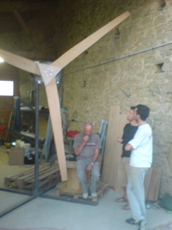
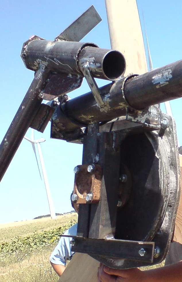
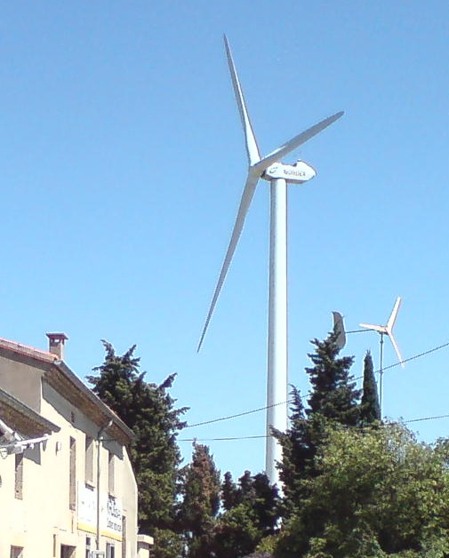
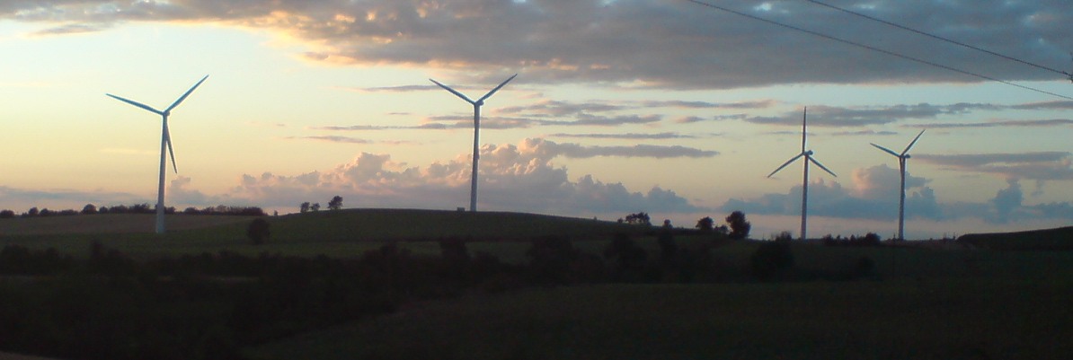
The machine produced 8kWh tuesday, and was at 9kWh for the
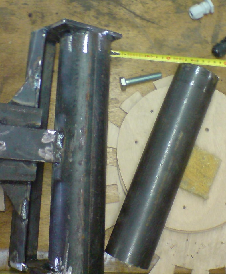
day when the tail broke just before noon Wednesday.  The machine had
several ten minute averages of between 1-1.2 kW.  Meaning the machine was
quite often producing the maximum capacity of the windy boy 1700.


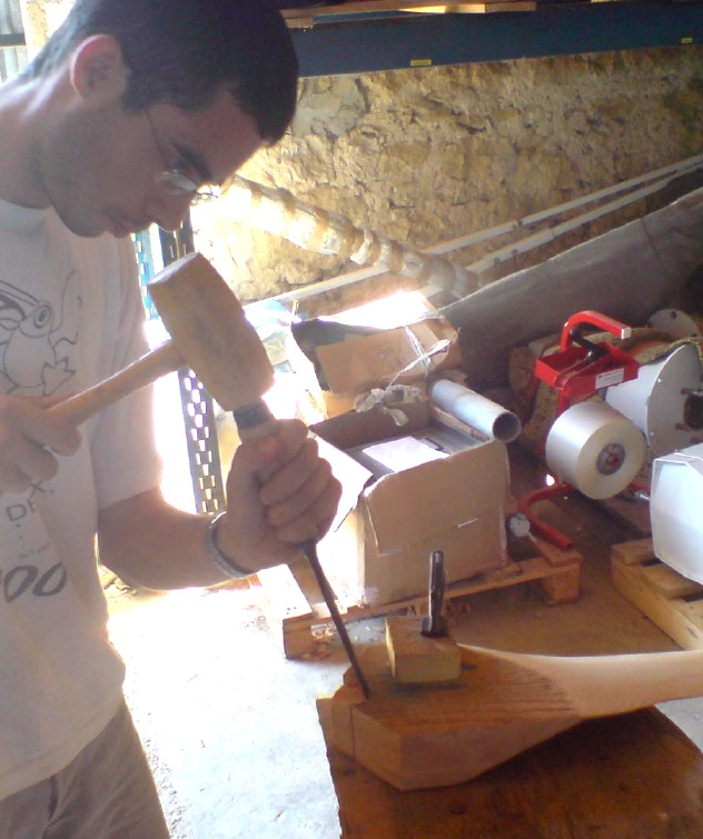
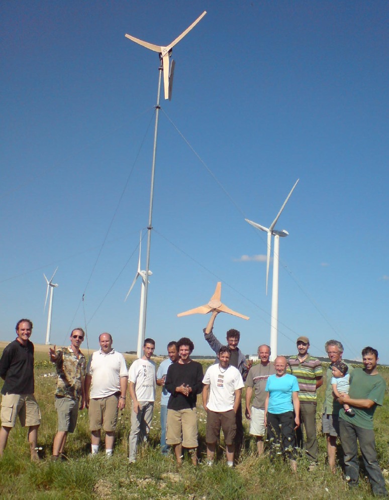
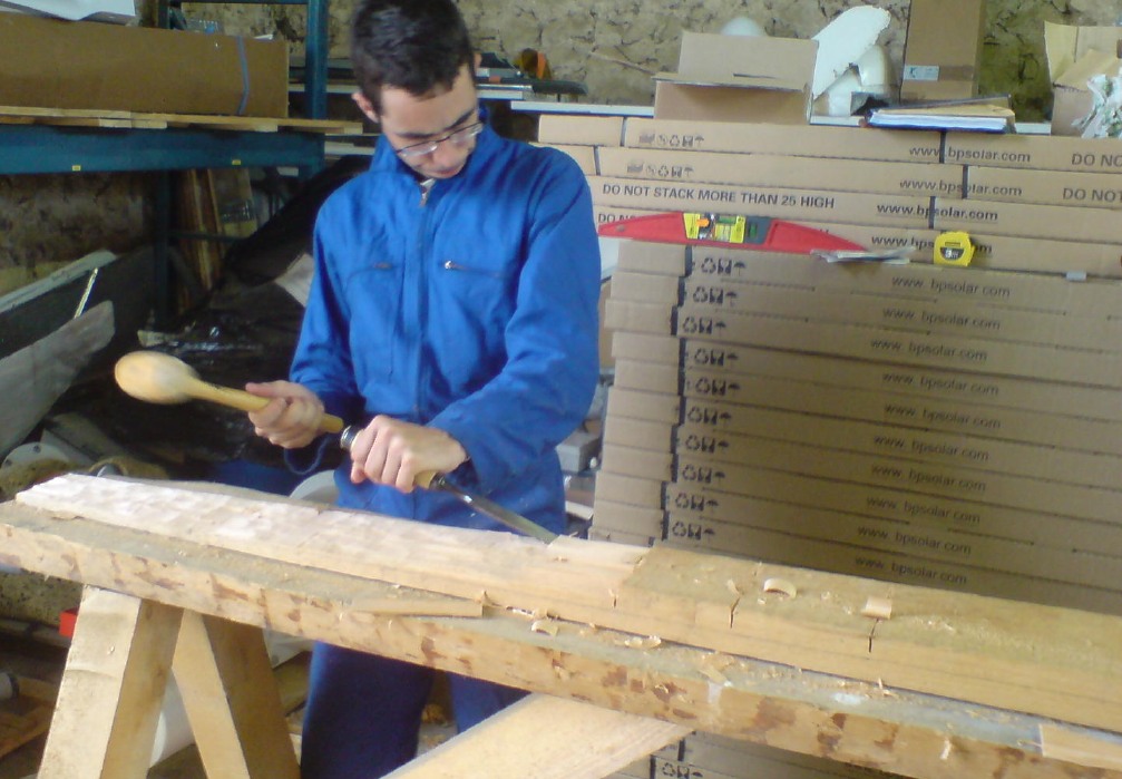
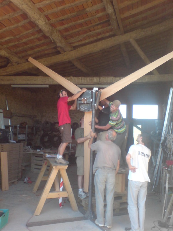
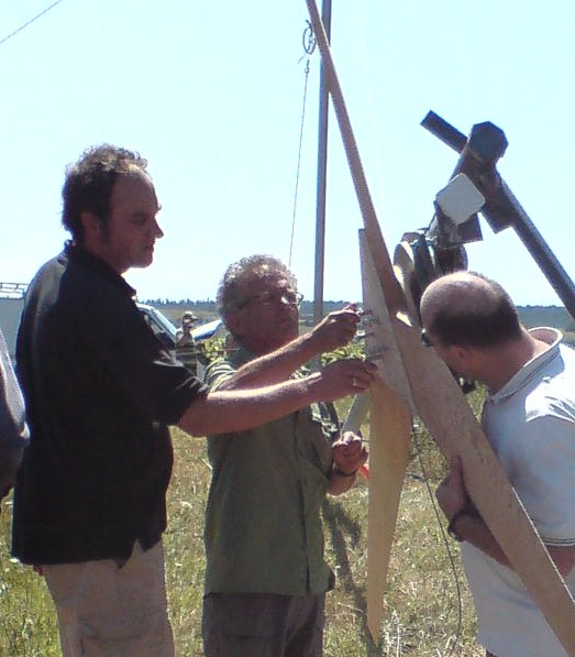
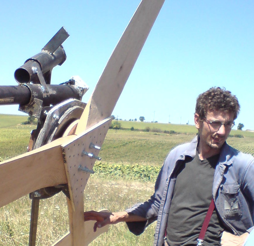
A new set of blades will be carved in
September and the machine will be installed more permanently after that.
Some welds failed on the tail hinge.  The hinge tipped over.  The tail jumped out and got into the blades.
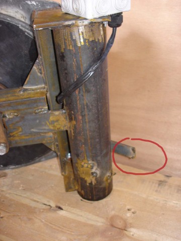
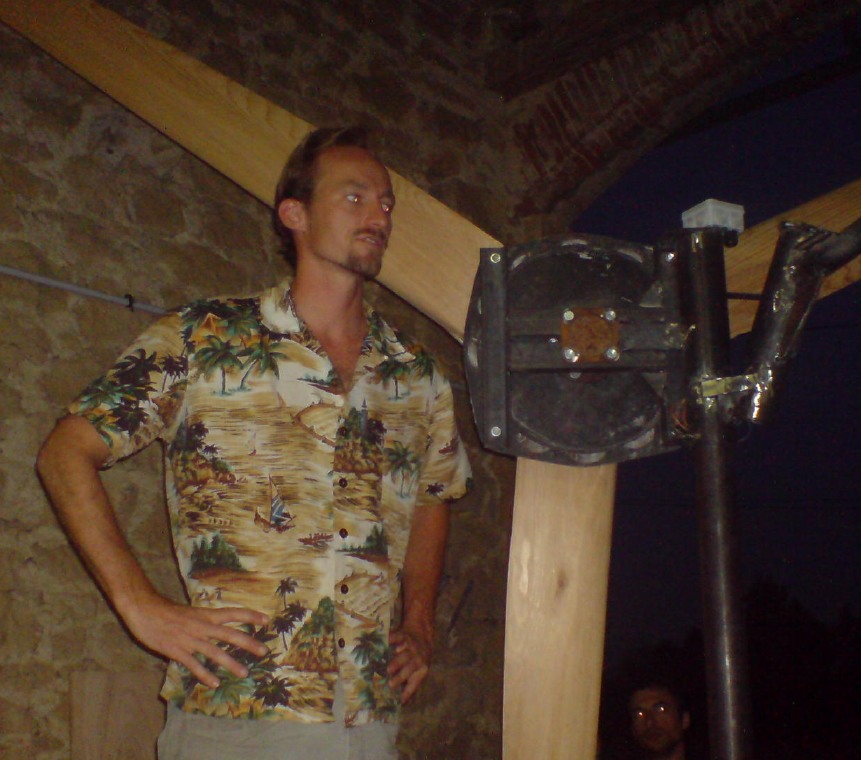
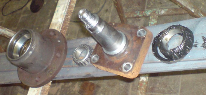
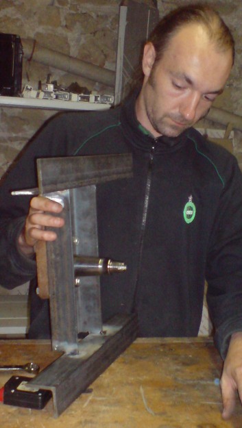
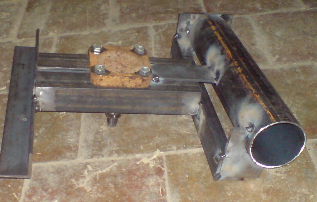
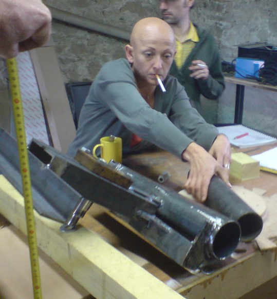
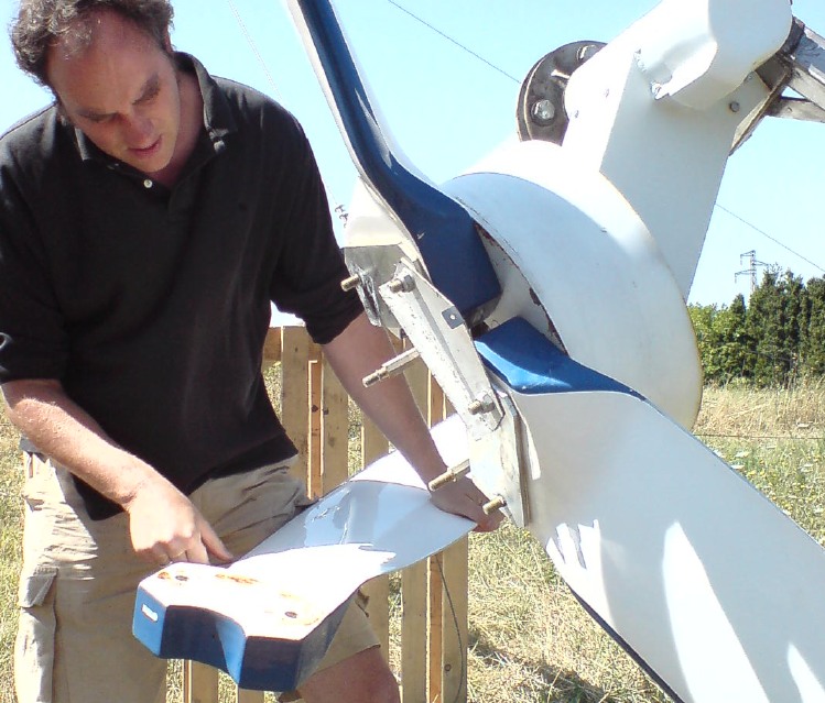
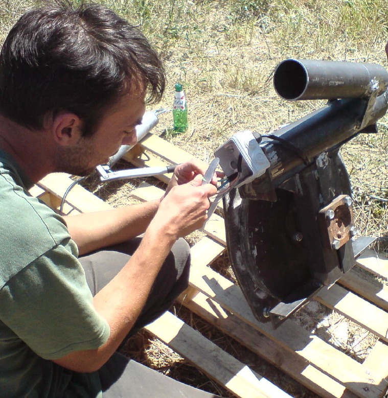
"Shit happens, always check the welds twice" says Jay.
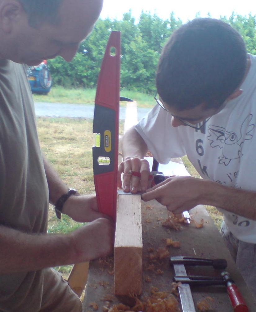
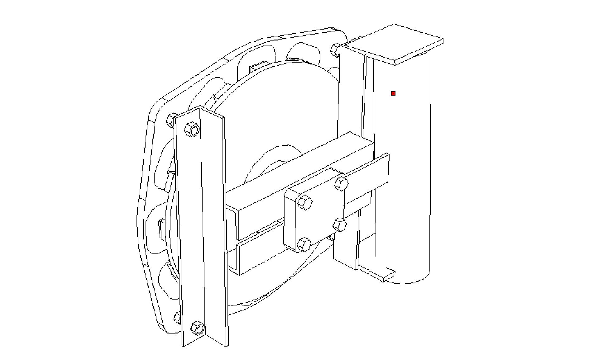
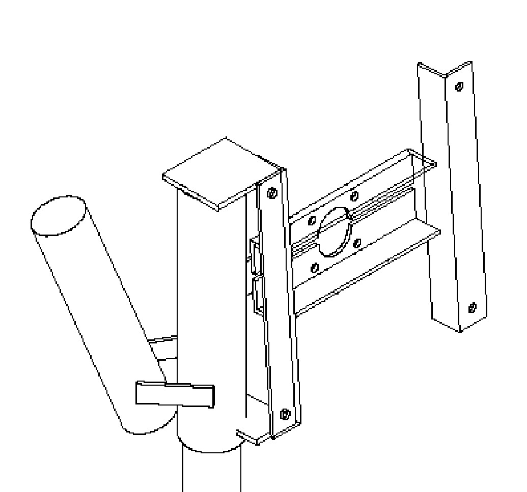
Next time make the supports for the tail hinge much stronger - it's very easy to do.  With hind-sight this part should have been more heavily built.  It's a part of the machine that often tends to fail if there is heavy vibration or any defects in the welding. 


SMALL TURBINE - PETITE EOLLIENE


Guy, Sylvain and Laurence work with coils in the stator mould.

Stator

The coils are 6 mm thick
They are wound on the same winder as the 4-metre turbine  (same 4 pins)
The wire size is again 0.71mm
The number of turns is 150
Connection is again series/star


Thomas trims the stator casting.


The construction is different from the older plans in that the magnets are mounted 'sideways' to increase the space in the middle, and the stator is mounted behind the magnet rotor (downwind) instead of in front on the windward side.  This is simpler to do and it all fits together nicely.  The hardest part is to set 3 studs into the stator.


I have inset two views into this shot.  The magnet rotor alone is top left, and the stator on the steel frame is top right.  In the centre the magnet rotor is added to the stator.

Pierre cuts out a space for the bearing at the centre of each blade.

The small machine was completed but never fully assembled because
Guy took it home.