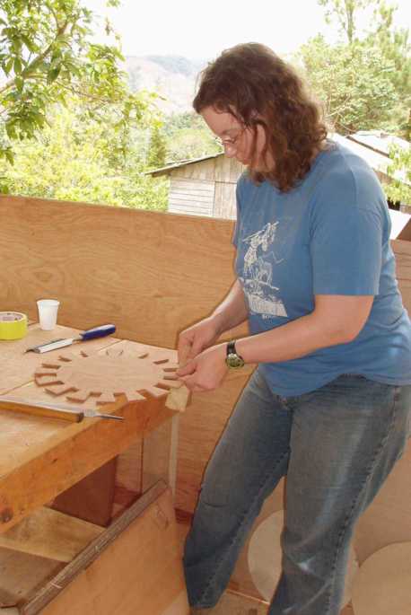
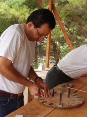
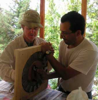
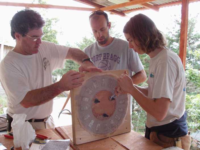
Melissa prepares the magnet template and Sergio inserts the magnets.
Sergio works for the national power utility.
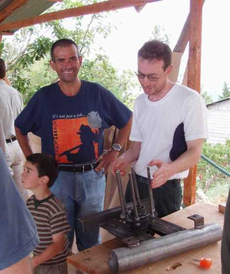
The stator for this 16 pole machine is square in shape. Here
a dummy stator is used to drill holes in the mounting lugs.
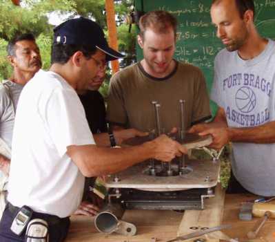
Amos, Eugenio and Ismael make sure that it is centred on the shaft by measuring
the space in each direction.

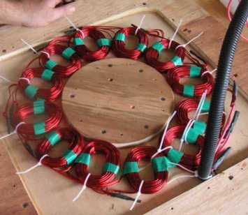
The stator has 12 coils. Each coil is wound with 25 turns, using
2 strands of #13 AWG copper winding wire. The four coils in each
phase are connected in series and then the phases are star (or wye) connected
to give a 3-phase output.
Jim Hogue and Sergio tighten the magnet rotor mould. It's tricky
working with a wrench in front of the magnets.
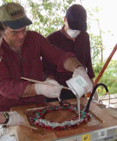
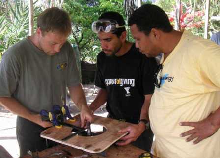
Brian Faley pouring resin. He has to be very sparing with the
use of catalyst because of the high ambient temperature and the shortage
of catalyst itself.
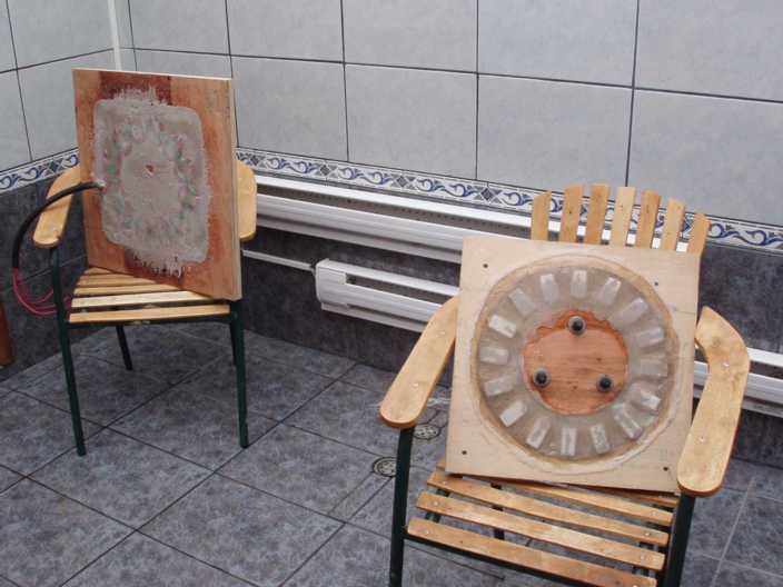
The completed castings curing in the heat of the sauna. The Durika
hydro turbine was dumping 6 kW of heat into the sauna all the time, in
spite of the low water in the stream.
Brian, Chirs and Ryan take the rotor out of its mould. Ryan has
to take care not to have the wrench grabbed by a magnet.

A completed magnet rotor latches on to the contents of Chris's pockets.
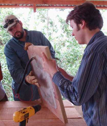
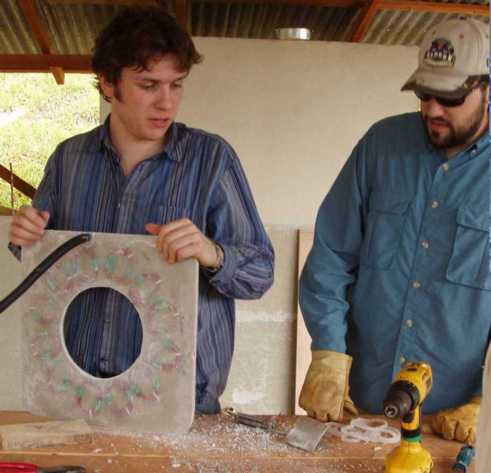
The stator coming out of its mould, helped by Jeff Homan and Mathias
Craig of blueEnergy .
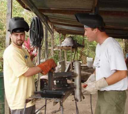
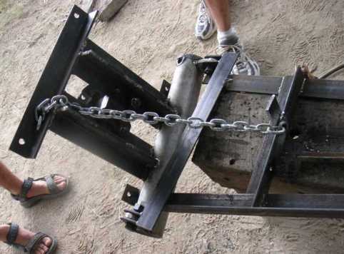
Guillaume Craig and Amos in the welding shop with the alternator frame
Carlos from Durika, and Aaron Eisenberg admire the welded frame.
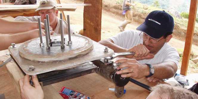
Below, Sergio fits the second magnet rotor with help from Joshua Lohr
and Chris Chavez.
The jacking screws are in place to protect their fingers from getting
trapped.
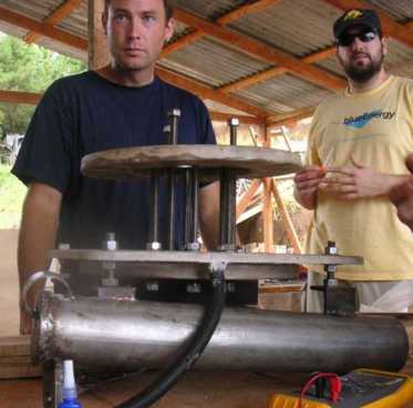
Amos and Jeff with the alternator partially assembled.
Sergio tightens the stator mounts after checking/adjusting the clearance
to the rotors.
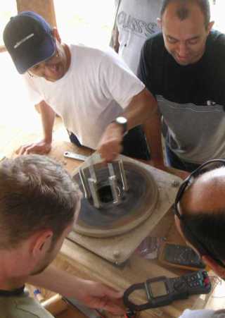
Sergio and Alexander spin the alternator while Joshua and Chris admire
the output waveform on a meter.
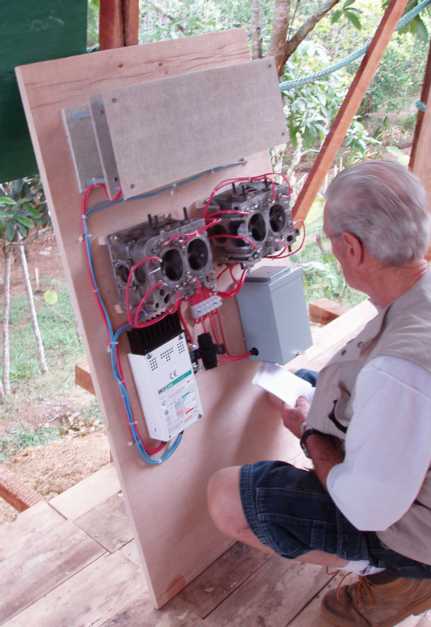
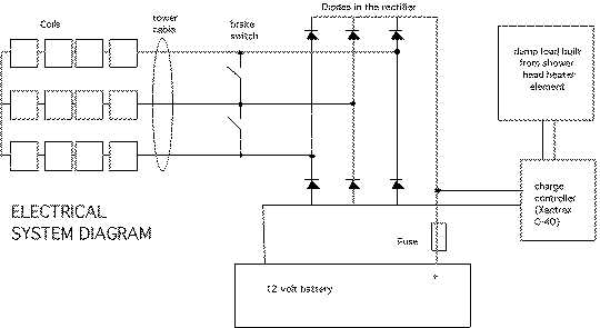
Bill roman checks out the controls. On the right is a brake switch
that is used to stop the turbine by shorting the 3 AC wires together.
In the centre are two halves of a car cylinder head with 50 amp diodes
pressed into them to make rectifiers. The castings are used as heat
sinks for the rectifier diodes. Each of the 3 AC phases is fed to
2 diodes on each heatsink. The Xantrex C-40 charge controller on the bottom
left diverts any surplus power to a dump load situated between slabs of
heat resisting material at the top.


 Back
to the main page
Back
to the main page