PROTOTYPE 'NIRVANA' ALTERNATOR PAGE 2
ERECTION SCORAIG
AUGUST 2004
and BURNOUT
OCTOBER
and back up in November
FOR CONSTRUCTION CLICK HERE
BLADE DIAMETER 5 metres / 16 feet
POWER 4000 watts at 220 rpm
28 magnets per rotor 46x30x10 mm ND40
(later rebuilt using 70x30x10 mm ND40)
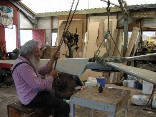
BLADE BALANCING
We've used these blades before, and we always balance them on a
spike. The blades are too big to balance vertically on their bearings
in
our workshops. Previously we balanced them and the alternator
rotor (truck wheel) together on a spike.
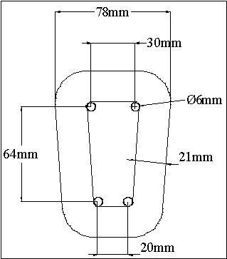
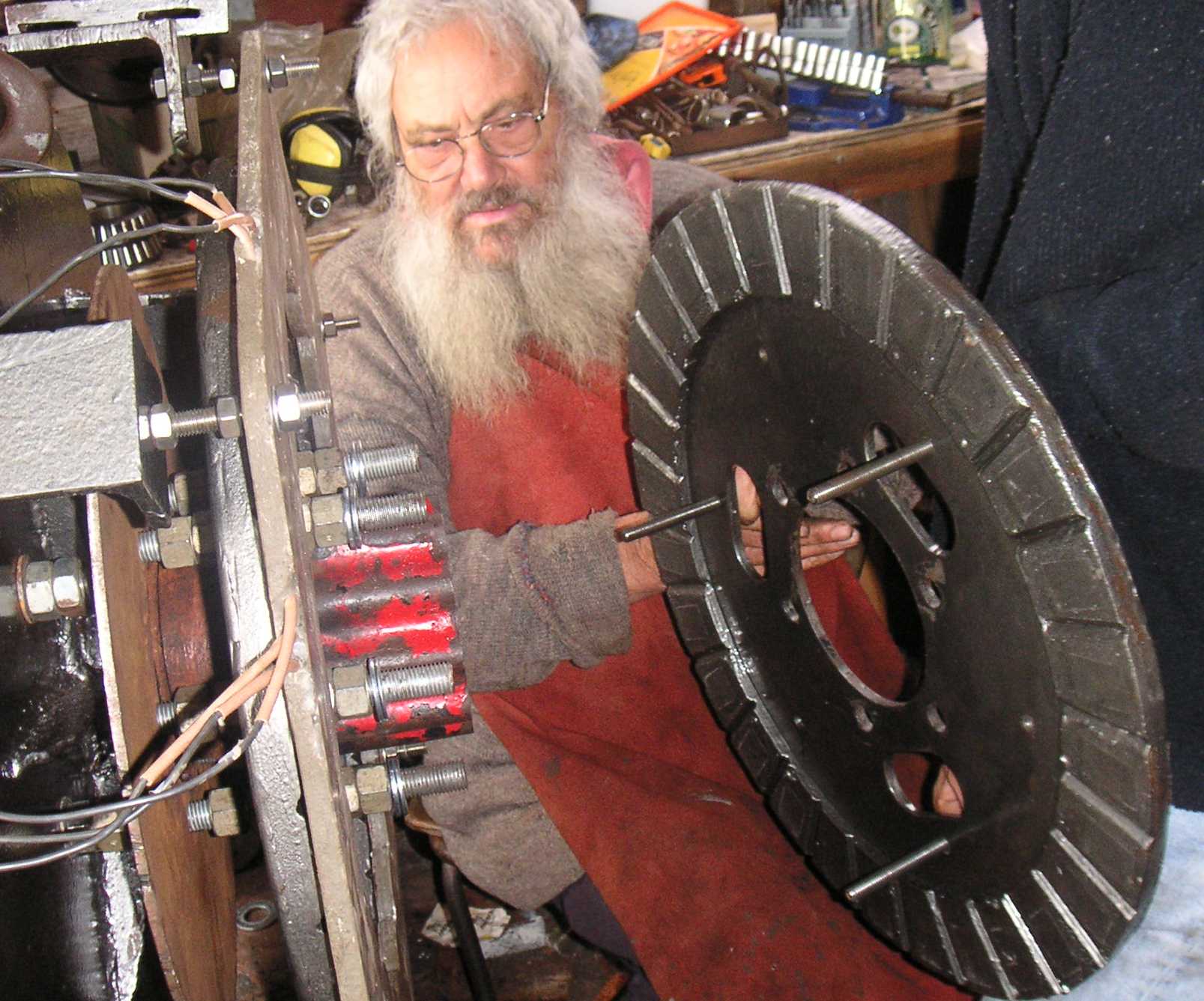
Here we use a steel plate that bolts onto the end of the wheel
hub where
the half shaft flange would normally bolt to. (You can see this
better
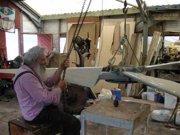
in pictures down below.) Alan is positioning the blades above the
spike so we can balance them. A chainhoist is ideal because even
if he could stand up (which he can't do much of due to his multiple
sclerosis)
he would not easily be able to hold it comfortably. The steel
plate
bolted to the blades is 1/2" thick. Alan likes thick plates.
The spike is a broken drill bit ,tapered to a point with a
grinder,
and fitted into a chuck. The chuck sits through a hole in the
bench.
We drilled a small hole at the exact centre of the ring of
mounting
holes in the steel plate and we rest the spike in the centre of the
hole
so as to make a pivot.
|
CLICK ON A PICTURE TO SEE IT FULL SIZE.
THIS IS A NEW FORMAT I AM TRYING OUT.
|
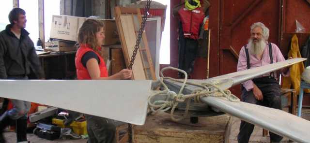
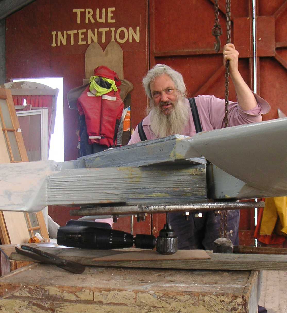
| Jonah and Rissa arrive to join the fun. |
 |
|
 |
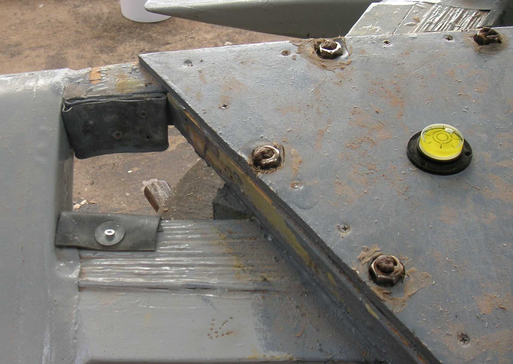
| Here you can see the spirit level we used. We hold it
so that
the bubble sits in the middle and then let go and see which way it
falls.
On the left you can see some sheet lead (flashing) that I screwed on to
balance the blades. In the end it would poise level without any
tendency
to fall one way rather than another. |
 |
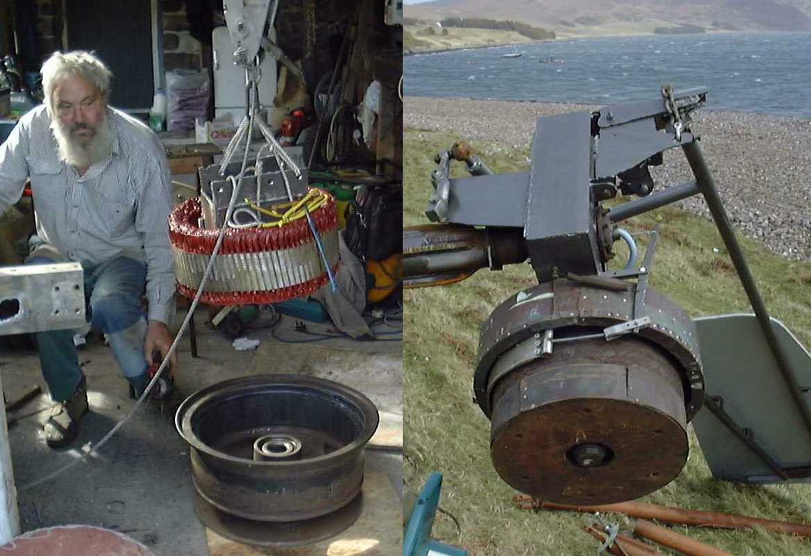
ALTERNATOR ASSEMBLY
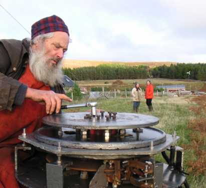
We balanced the alternator rotors on their bearings. Putting
it back together we used more washers than before to make sure there
was
plenty of clearance between rotors and stator. We may have
over-done
it slightly. We'd get more flux, and thus lower speed with a
smaller
gap. But better safe than sorry.
|
 |
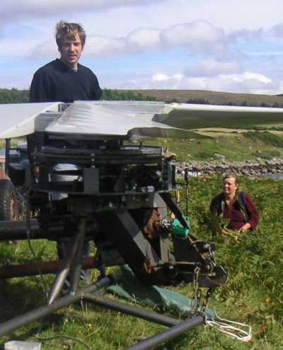
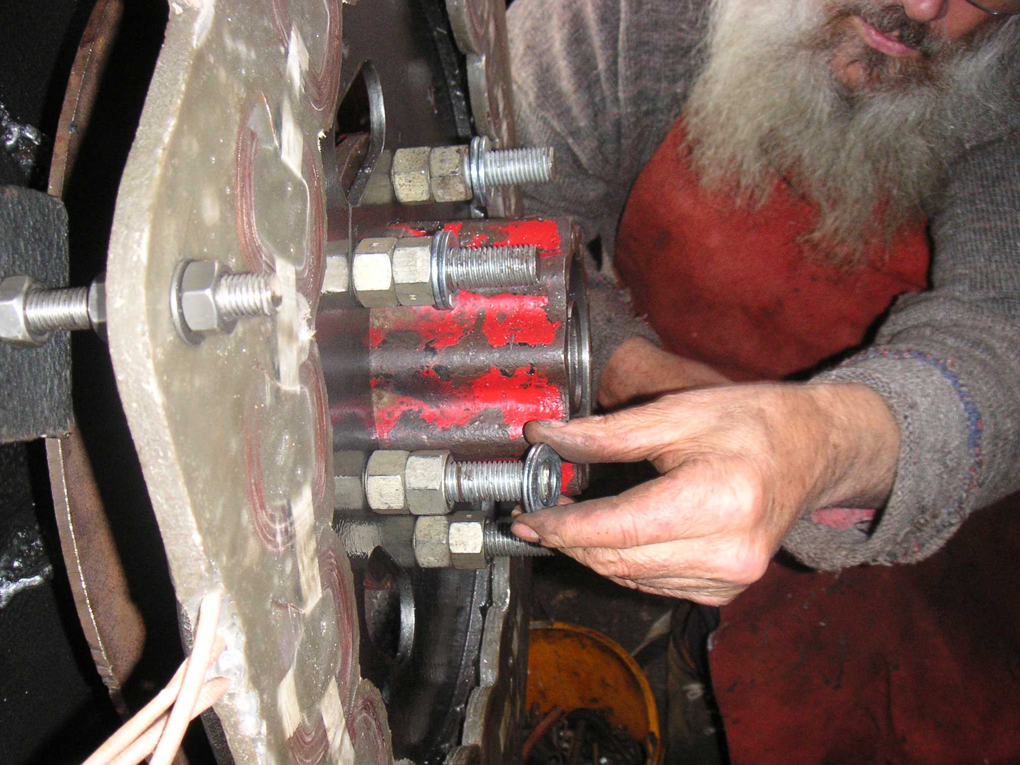
| Fitting the front rotor. Notice how Alan and Jonah hold
the rotor
by the jacking screws and keep their fingers out of the gap. If
it
tilts sideways and the rotor bangs onto the stator you don't want your
fingers in there. If you are careful you can keep it straight. |
 |
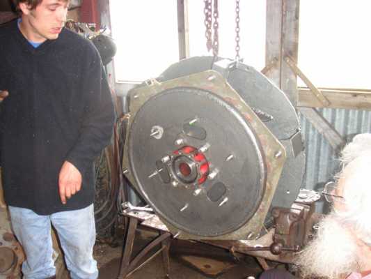
| Ready to roll. Notice the small balancing weight on the
magnet
rotor (and the ten o'clock position). |
 |
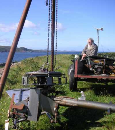
| Using the chain hoist to transfer the alternator onto the
frame of
the windmill. |
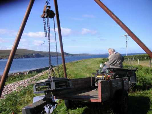 |
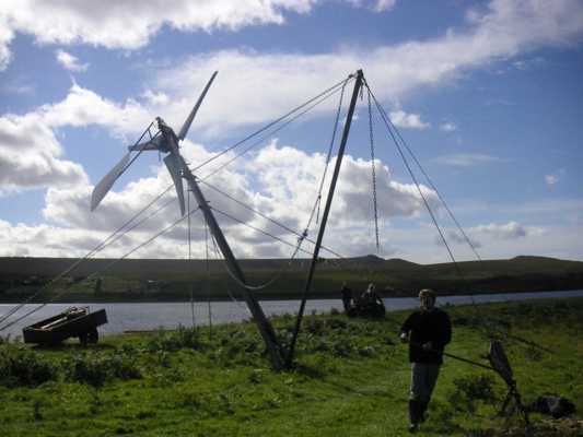
| You can see Alan's windmill in the background. This one is
for his
son Martin. When one is out of action they can charge the
batteries
in both houses off the other one, because the electrical systems are
the
same. |
 |
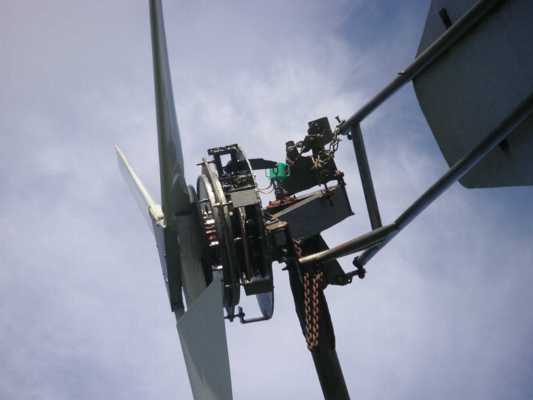
| This windmill now has a disk brake. It's a lot more
hassle than
the band brake we used on the truck wheel alternators. Look at
all
the levers and adjusters.
It's a great feature to have a mechanical brake. We
could probably
use a short circuit, but these blades have a huge torque. And we
want to be able to stop it even if the wires come disconnected.
|
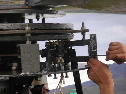 |
| We had to beef up the main brake lever to 1/2" plate after
initial
trials bent the first one. Jonah had to make the hole in the backplate
bigger to fit the new lever.
The Danish guy in the background was very puzzled. He
told me
later "What you were doing today was engineering - but you are not
engineers!"
He just could not get it.
|
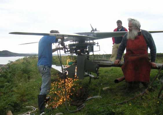 |
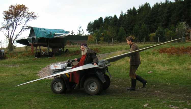
| An end-view of the big blades. They are not solid
wood.
That would weigh a ton. They are made from plywood with a central
spar. |
 |
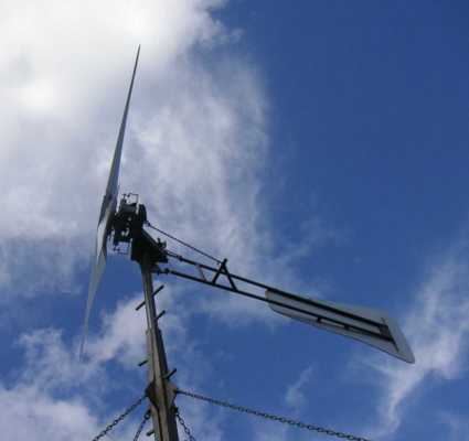
| On its way up...
The chain is the low end stop for the tail. It all works
with
heavy chains and pieces of steel plate.
|
 |
| Jonah cranks the hoist. It's hard work. My turn
next. |
 |
| Up and running at last.
See below for further comments.
|
 |
SOME STUFF ABOUT THE WINDMILL AND ELECTRICAL SYSTEM
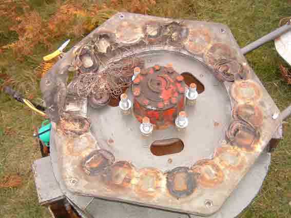
HERE IS THE ORIGINAL ALTERNATOR WE BUILT FOR THE MACHINE
BUT IT GOT DESTROYED WHEN A BLADE CAME OFF EARLY ON.
I WON'T SAY WHO MADE THAT BLADE :-)
NOTICE THE BAND BRAKE ON THE OUTSIDE OF THE WHEEL. VERY
SIMPLE.
AND HERE IS A DIAGRAM OF THE ELECTRICAL SYSTEM THAT CONVERTS THE
OUTPUT
INTO HEAT AND BATTERY POWER.
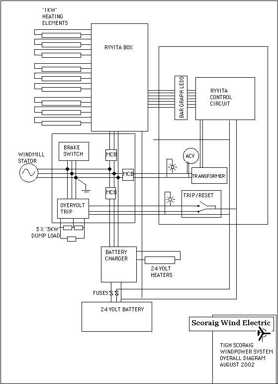
MCB MEANS 'MINIATURE CIRCUIT BREAKER' RYVITA MEANS CONTROL
CIRCUIT.
THE BATTERY CHARGER IS CONTROLLED BY A BATTERY VOLTAGE SENSOR THAT
TURNS IT ON OR DIVERTS TO ANOTHER HEATER IF IT GETS TOO HIGH.
PERFORMANCE DATA
The stator puts out about 1 volt rms for each rpm of speed. this
translates into about 1.4 volts DC. So at 200 rpm you can get
about
280 volts DC open circuit.
In reality it is loaded so the voltage is lower. The battery
charging
transformers are set up so that it starts to charge batteries at about
70 rpm. The first ryvita heater cuts in soon after but the others
wait until the DC voltage is up a bit higher. By this time the
battery
charger is going strong and the 24 volt heater in series with the
battery
is hot.
Frequency is related to rpm, so I measure the blade speed using
Hz.
60 rpm is one rev per second is 14 Hz (28 magnet poles give 14 cycles
every
revolution). At 63 Hz or 270 rpm I read 16.9 amps rms which
translates
into 21 amps DC at 280 volts or 5,900 watts. My wattmeter reached
7 kW at one point. But I prefer if the average power is more like
4kW. I don't want to melt the stator.
Next alternator we build will be the same size but we'll use
slightly
larger magnets 70 x 30 x 10 mm, and this will greatly improve the
efficiency
and allow us to run slower (nice) and also get more power.
LATEST NEWS - ALTERNATOR DID
BURN OUT FINALLY.
THE CONTROL SYSTEM HAD JUST BEEN ADJUSTED TO BRING THE SPEED DOWN
AND
AND CURRENT UP.
WE NEED TO REVERSE THIS AND MAKE THE TAIL FURL SOONER - BOTH EASY TO
DO.
IN THE LONGER TERM WE SHALL ADD MORE MAGNETS. I AM CONSIDERING
DOING A DOUBLE DECKER ARRANGEMENT ON ONE ROTOR TO GET A BIT MORE
FLUX.
BUT THE LONGER MAGNETS WILL BE A BETTER SOLUTION IN FUTURE.
We have to make this alternator more efficient.
re-erection in November 2004
new stator wound and fitted

back in action
but see this
link for the latest issues with magnets in 2006
In 2007 I can say that we have built a few alternators based on the
longer 70 mm magnets and using 80 turns of 1.6mm wire (14AWG).
The outer diameter of the magnet rotor is unchanged as 588 mm.
The coil former is an interesting shape to squeeze in so many turns.
back to my home page
back to page one which describes how the alternator
was built

