Once again we assembled to build a small wind machine.
Brian Faley of Shoreline Power Design came
from Washington State USA to help teach.
Julius Tangka came from Cameroon in Africa.
Uwe and Stephan came from Germany (different cities).
John came from Denmark (John was also on the CAT 2002 course).
Giuseppe came from Rome.
Demian came from Edinburgh.
A number of other folk booked in for the course and then later cancelled.
This is the smallest course I have done.
Here you will find some familiar pictures because the activities are
much the same as we always do, but there are always some new ideas.
Notes from this course are now for sale at this link.
NEW
- APRIL 2004 - PICTURES OF THE AFTERMATH - WHAT HAPPENED NEXT...
Captions for the pictures below were written
by Stephan Gilbert - Thanks, Stephan!
Stephan has also prepared a small
site with pictures of the course.
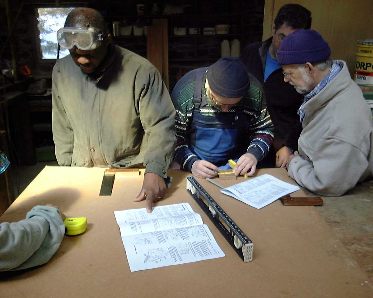
Pic 1: actually a very nice way to start the course, becoming familiar with the manual with Hugh's help by building the coil winding tool and the different pieces of plywood for the the rotor and stator moulds, it's perfect to start feeling comfortable with the tools available in the workshop.
(Here we see Julius Tangka, Uwe and John, with Brian behind - Hugh)
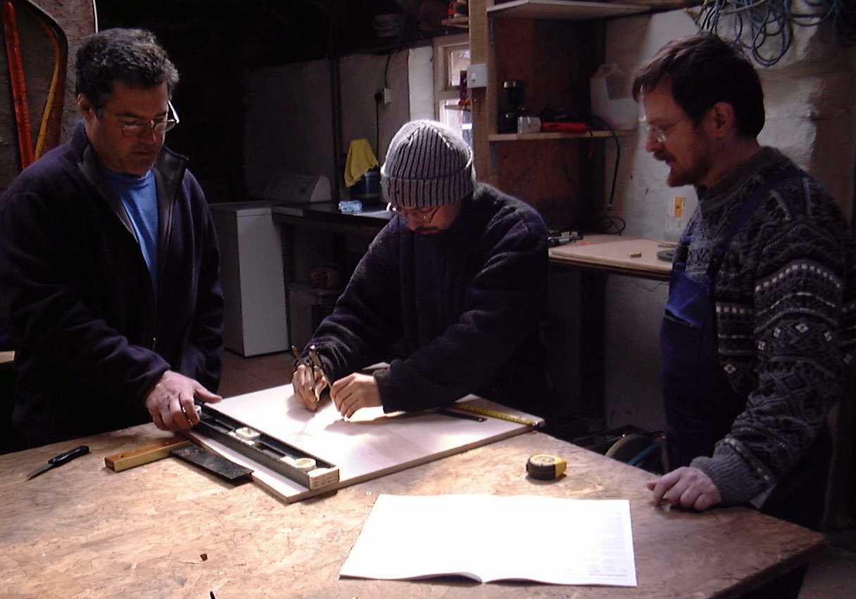
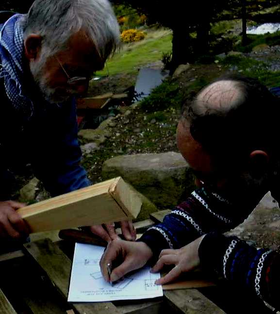
Pic 2: quite challenging to convert drawings into real size shapes, where do you draw and where do you cut? Also learning to use perhaps unfamiliar aids. With one precise angle on a piece of ply between two cuts all other lines and dimensions can be drawn using a simple angle and ruler. The beauty of the design as we found out during the course lies in the generous error margins allowed and required when working mostly with generally available hand tools.
(Here we see Brian, Demian and Stephan - Hugh)
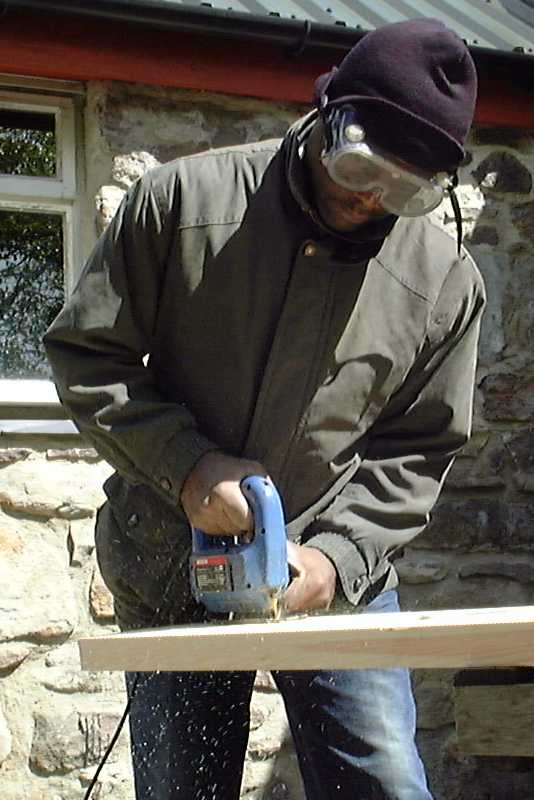
Pic 3: The jigsaw seems the perfect starter-power-tool. One can control
the direction and speed precisely. At the beginning it seems affording some
time and patience but the results are more than rewarding. For long and straight cuts we mostly used a circular saw.
(Personally I would not recommend using the jig saw here because it is slow and hard to steer - Hugh).
Pic 4: The magnet jig needs to be fabricated with high accuracy. During the placement of the extremely powerful Neodymium magnets on the the steel disks we noticed that the positioning errors of the strong magnets would have been difficult to reverse by trying to remove them before reworking the jig.
(John holds the improvised mallet, and Uwe the punch - Hugh)
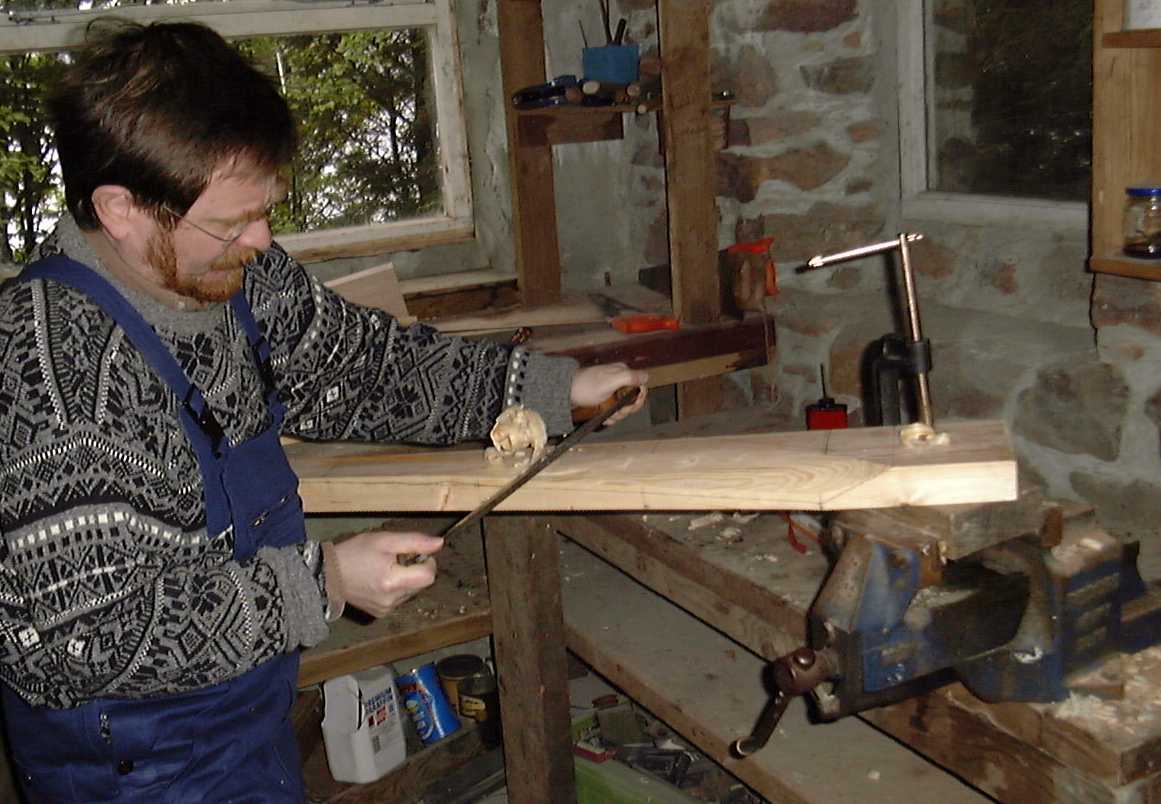
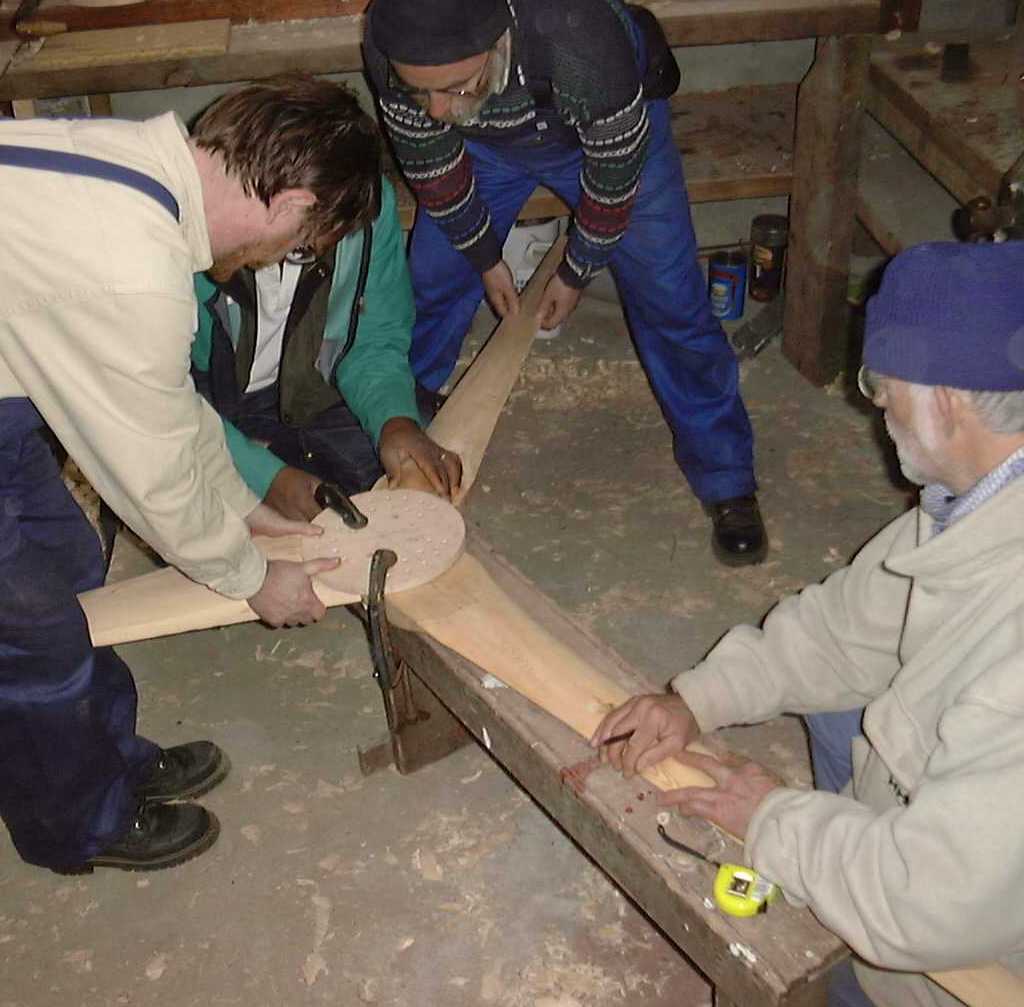
Pic 5: The drawknife gives you a lot of control, coarse and fine. The grain of the wood tells you in which direction to work, it's what one needs to watch for very closely especially around knots. The blade takes on shape rapidly and precisely ready for finer work with other tools. Learning to work in harmony with the wood feels very rewarding and natural.
(Stephan himself is at the handles of the knife.)
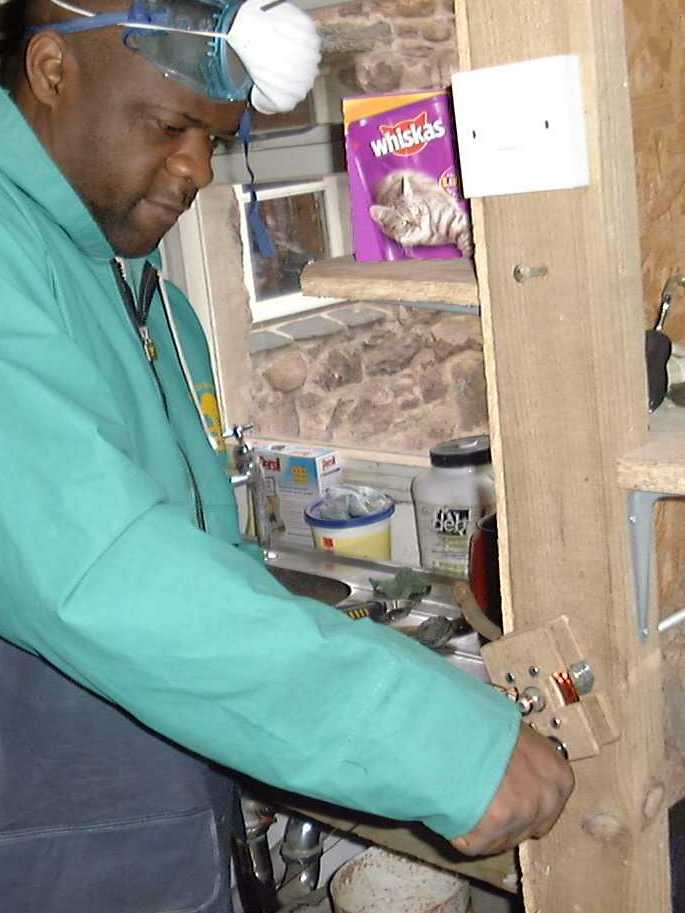
Pic 6: The winding of coils generated a lot of questions. How can you make
sure to correctly count all the turns? What tension should the wire have while
winding? How can we make sure the coils all have the same number of turns?
Well, the best measure is weight and a scale came in just handy. After winding the coils we compared the weights to make sure the person winding used the right amount of wire. But induction is proportional to the number of turns, would the number of turns be the same even though the weight is within tolerances? By the way, we wound 24 V coils. Since the coils will not be paralleled before rectification, differences in the number of turns are not so critical. Again, design tolerance where it's needed.
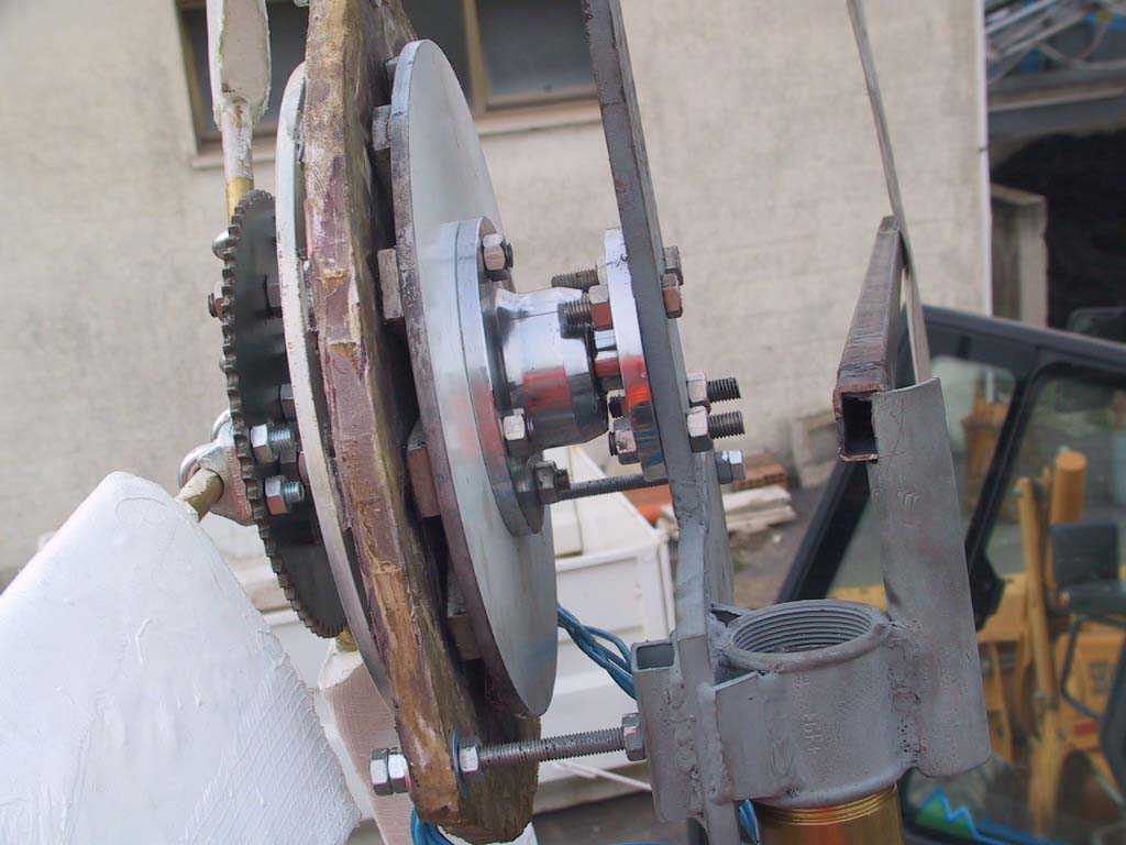
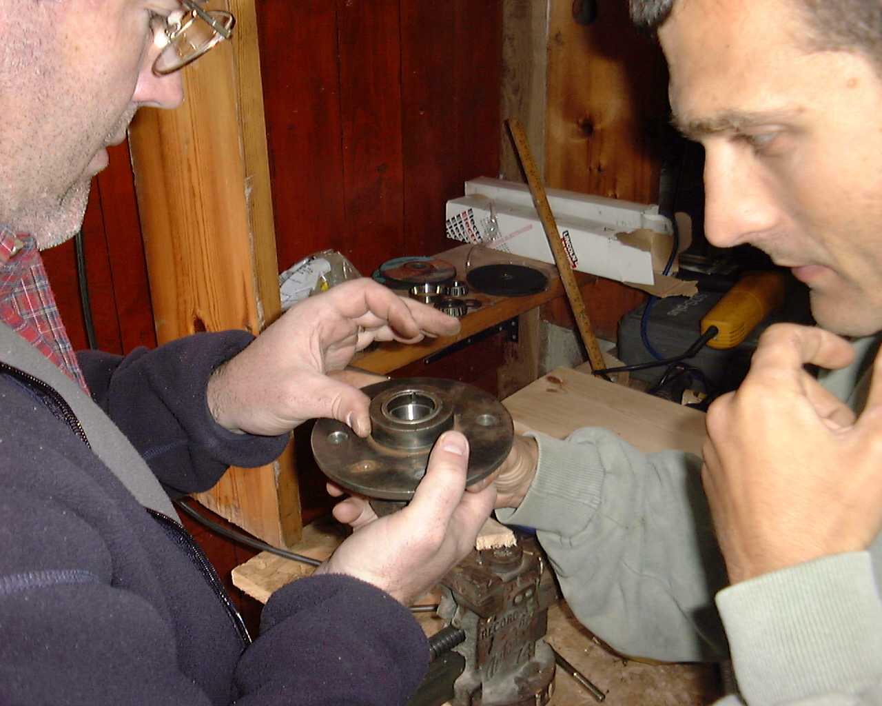
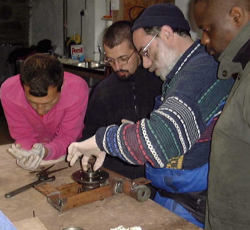
Pic 7: the hub looks like new after having been treated to a prolonged workout with an angle grinder. Unfortunately most hubs one will find at scrap yards will have worn races, with the help of inexpensive new ones our problems where solved after gently packing them with just the right amount of grease.
(Here Brian is using the old bearing race, split on one side, as a drift to knock in the new one. - Hugh)
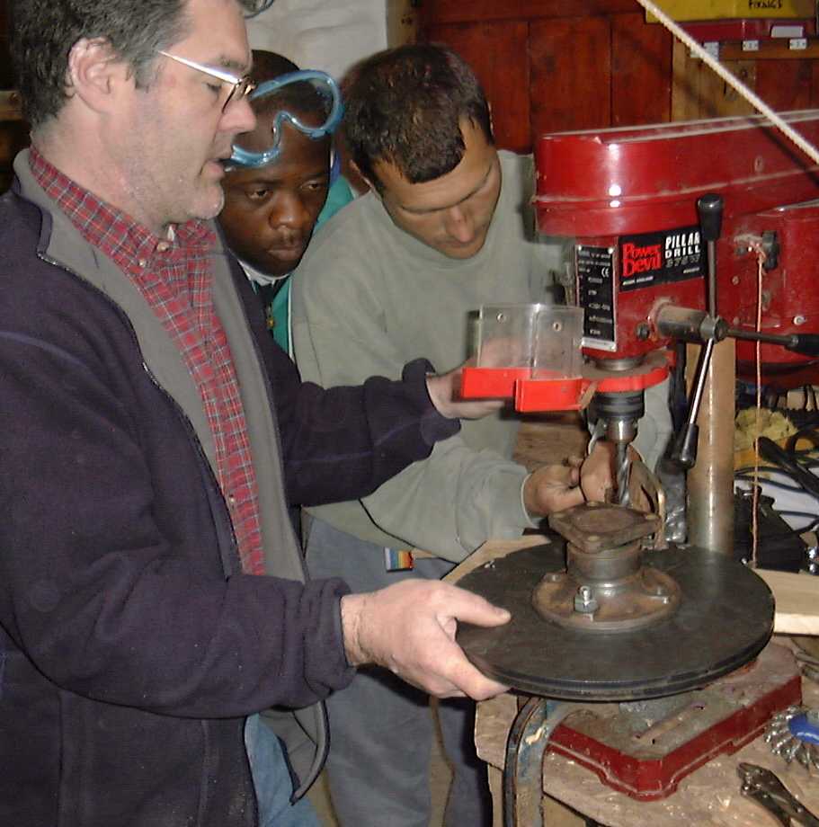
Pic 8: The beautifully laser cut extra thick steel rotor plates are drilled with the help of an often used self aligning technique. One hole is drilled through both plates and the hub for alignment (you can see the bolt holding everything in place). After aligning all three pieces, the 3 remaining holes are drilled.
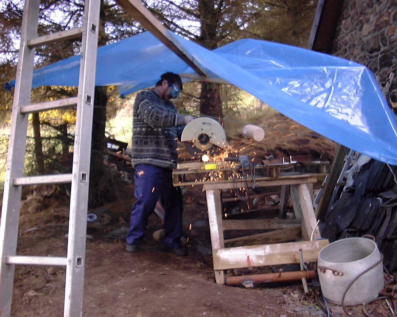
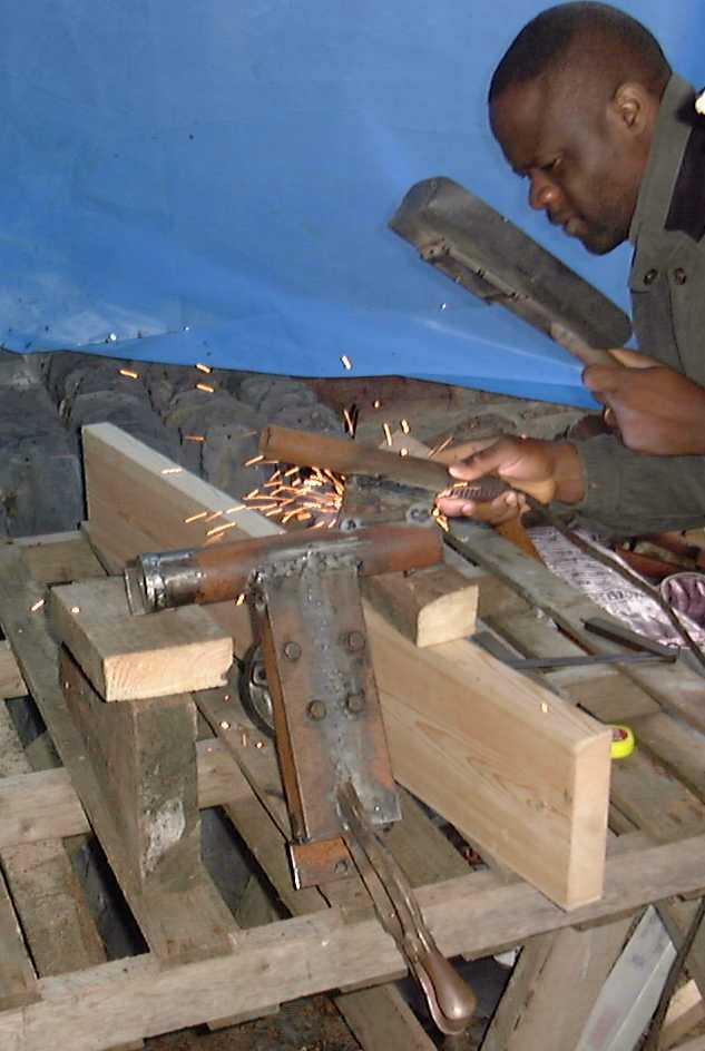
Pic 9/10: First one is impressed by the force and speed (and noise) of these very powerful tools, but after trying the hack saw on impressive 6 mm steel bars (and not having to start up the petrol powered generator) the choice is clear: the hack saw wins!
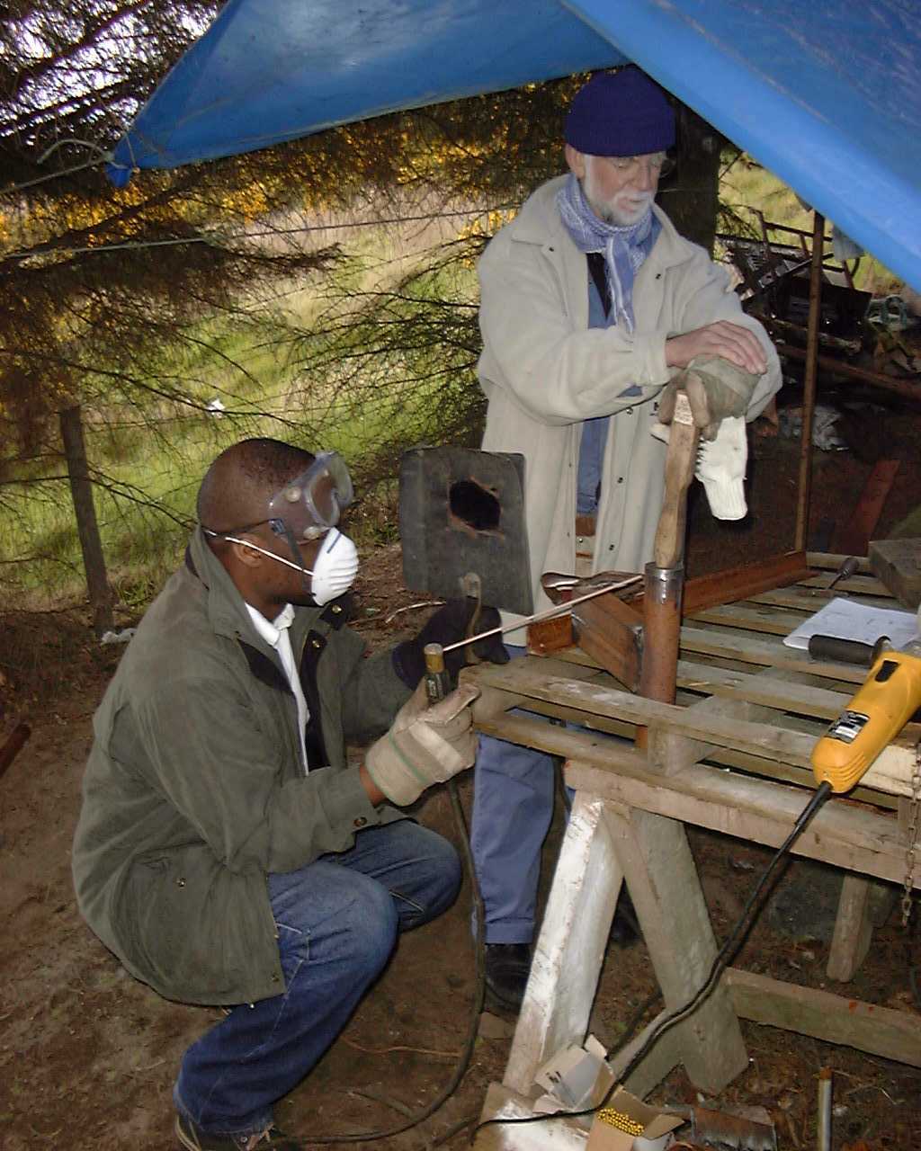
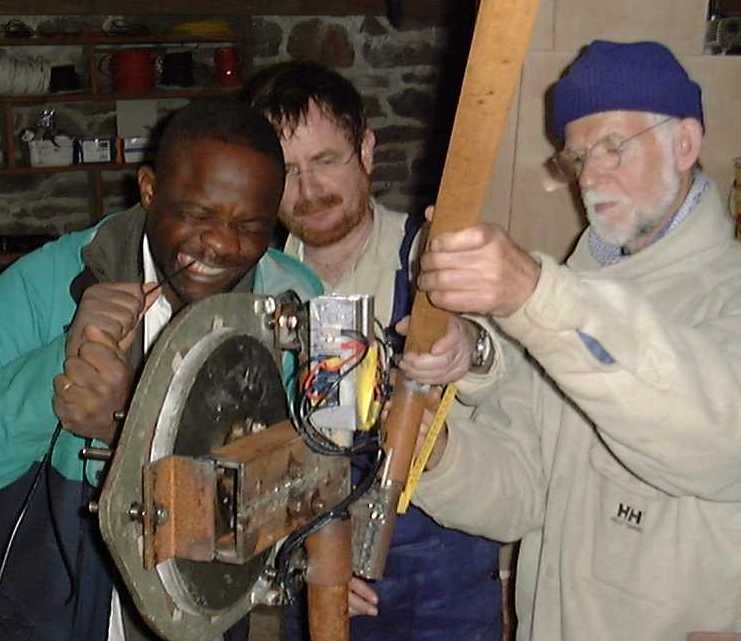
Pic 11: Fully protected Julius Tangka really is a fine welder but not without the help of John though! A few parts have already been assembled, the two "L" shaped brackets have been welded to became a "U" shape one (which will hold the alternator), the cylinder to turn on top of the pole and the top ring piece (which Julius Tangka is getting ready to weld) will prevent the wind turbine from sliding down the pole, oups!
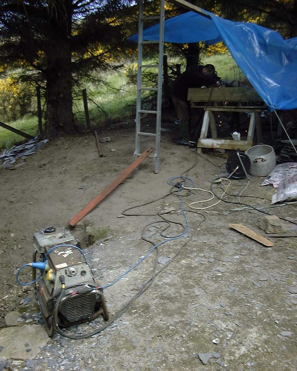
Pic 12: Demian also proved to be a talented welder. These little gas powered generators can become real life savers when everything else fails. A litre or less of petrol and you can do all the welding, cutting, lighting, you name it!
(My poor, neglected welding engine is over ten years old and it's always a miracle when it does the job!
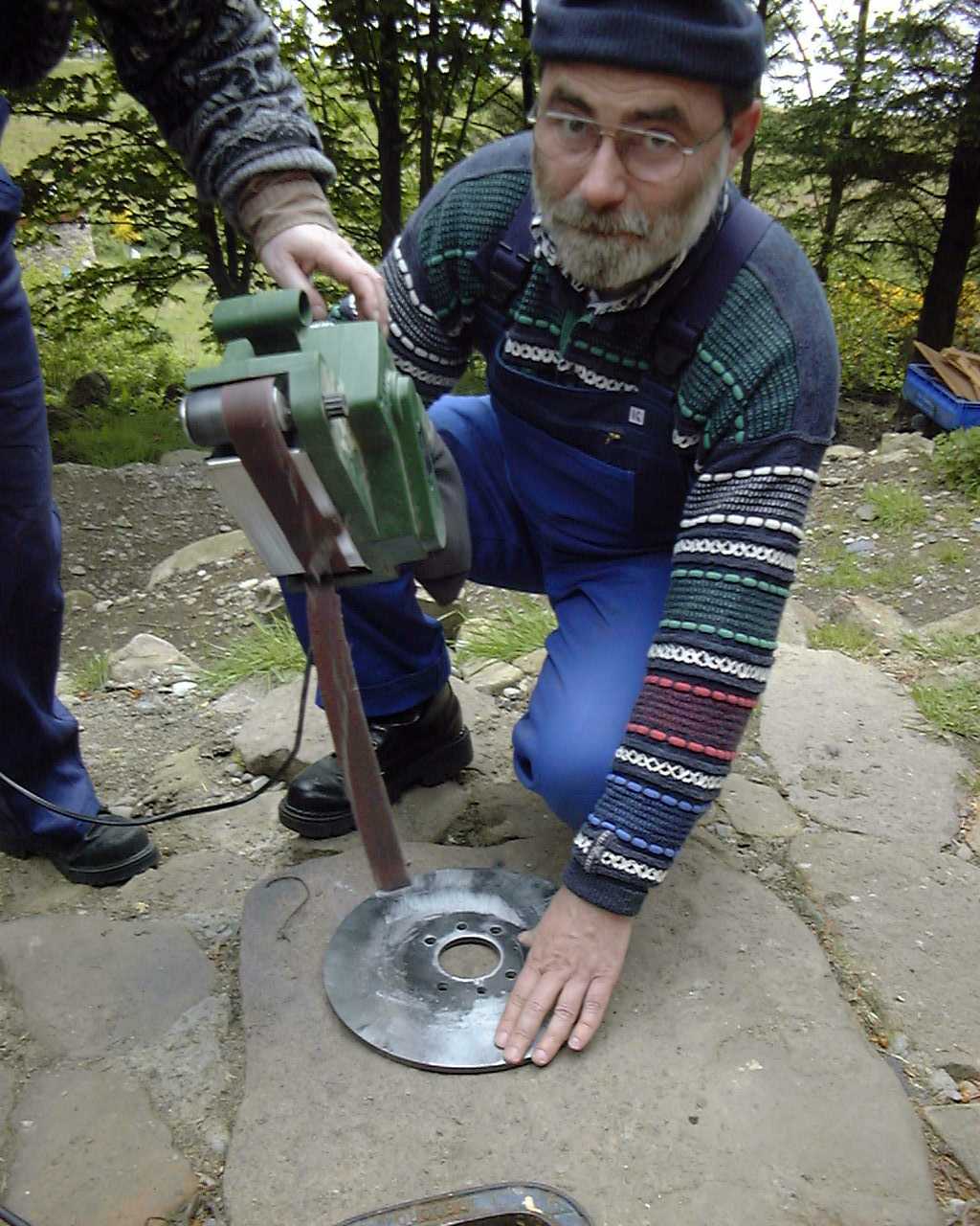
Pic 13: Uwe showed a lot of endurance in polishing the stator disks, belts were replaced more than once. The disks finally lost the self-oxidizing layer which could impair the magnetic flux and the belt sander gave up its life.
(We remove the oxide layer to improve adhesion. The sander works well if you press down hard. I finally wrecked the sander myself by hitting a sharp edge and tearing the belt. The belt then tore up the rubber roller. - Hugh)
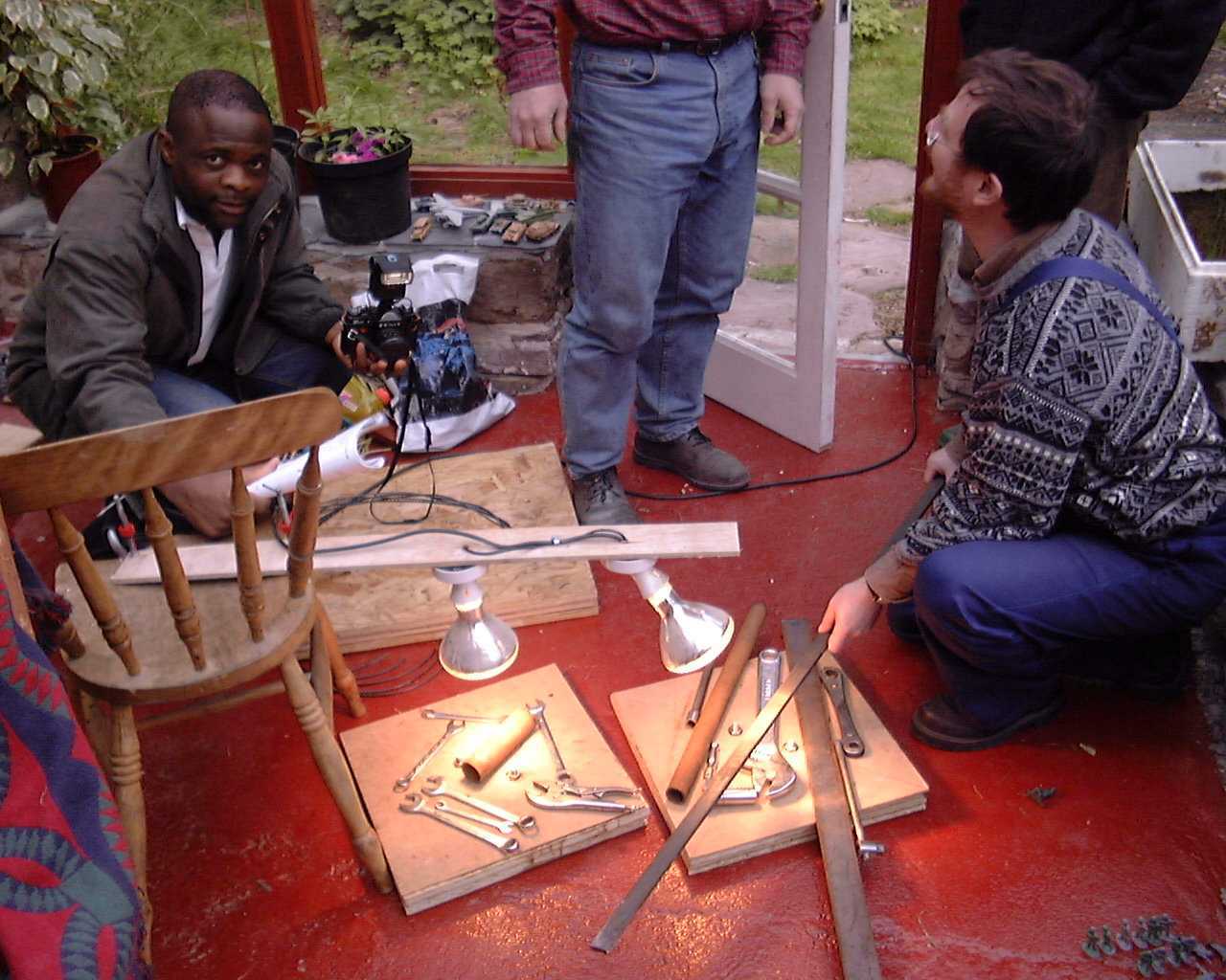
Pic 14: The metal tools were attracted by the magnets creating a force pressing
the moulds together. The 2 rotor moulds are in the front, the stator mould
behind. To help curing the resin we installed two heating lamps in William's winter garden. A beautiful tour of Scoraig's wind turbines was scheduled for the next day to give the resin more time to harden.
Pic 16: The reusable stator moulds have been opened, it turned out just perfect. After pouring the resin it is important to vibrate the moulds so air bubbles can rise to the top. Neodymium magnets will deteriorate when exposed to harsh environments, the resin not only prevents the magnets from flying away but also from aging.
(Neodymium magnets suffer deterioration if water manages to penetrate the protective coating. Embedding them in resin seems a good idea. - Hugh)
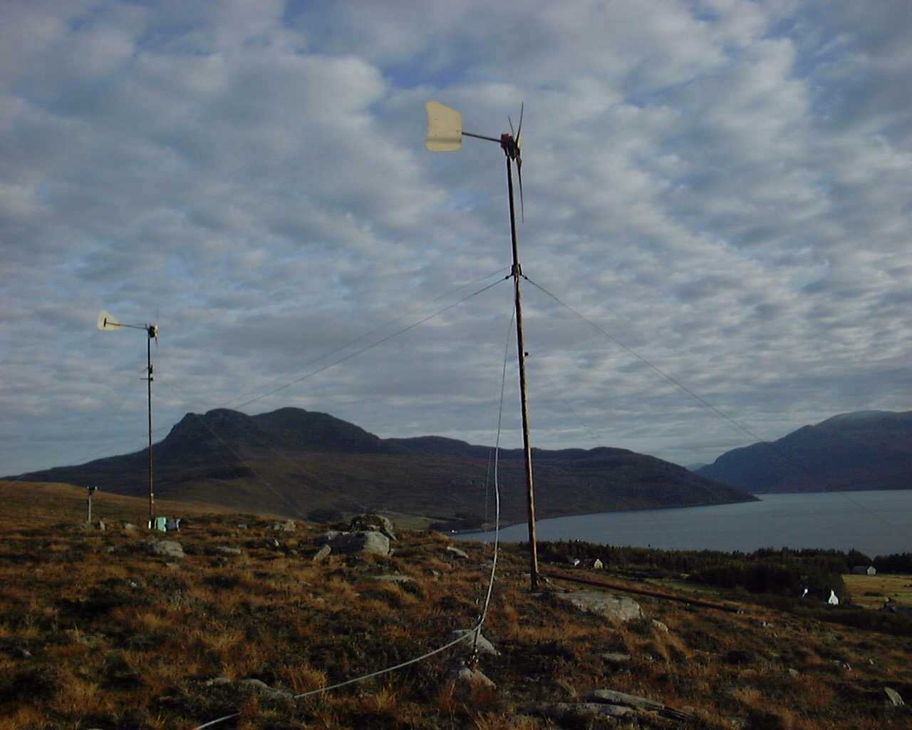
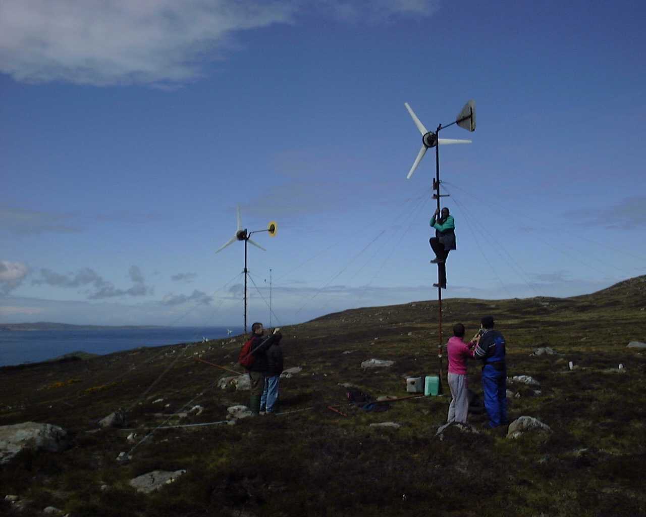
Pic 17: What great weather we had to explore all the different wind turbines on the peninsula...
Julius Tangka is showing off his pole climbing skills, Giuseppe
followed just after. We truly enjoyed meeting original "Scoraigians"
and were impressed to see that wind turbines - self-built, restored
and commercial ones - were in full use to meet power needs from
small dwellings to school houses. At the end of our visit, Allan Bush
welcomed us in his unique home and offered us refreshing tea.
Pic 18: The correct amount of grease keeps the friction in the bearings low.
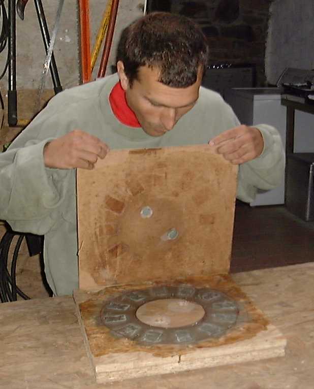
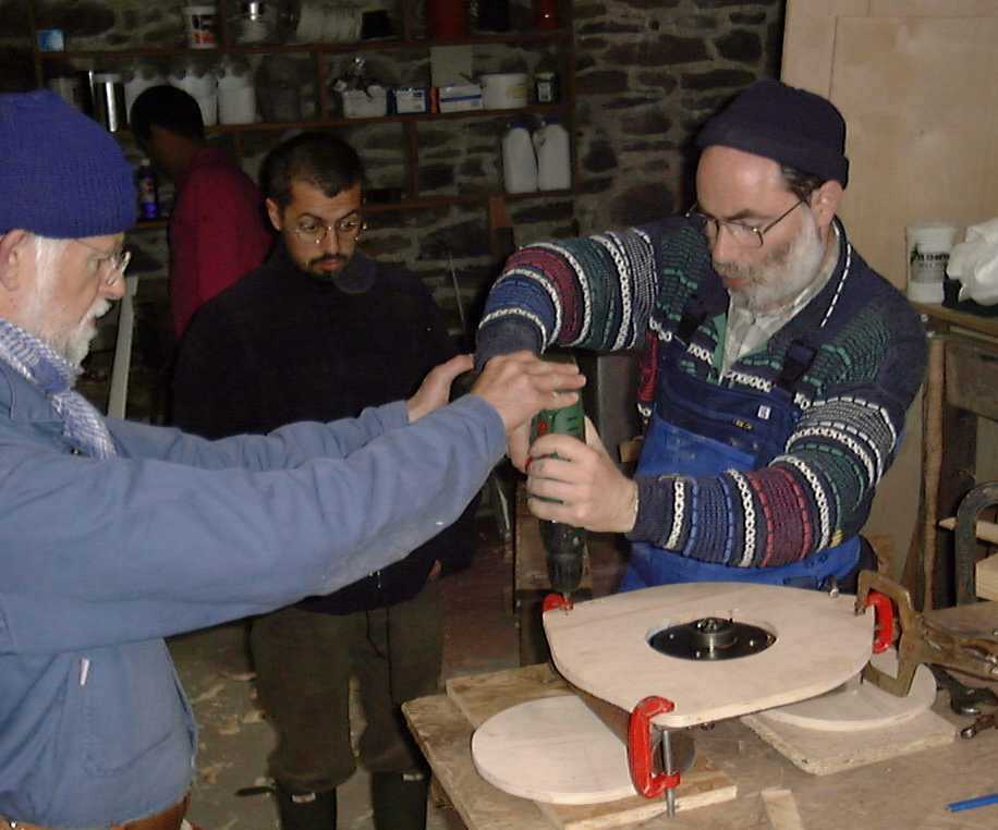
Pic 19: The wooden stator cut out comes in really handy when drilling the
mounting holes. Demian and John are standing at a right angle to each other to help Uwe align the power drill vertically.
Pic 20: Nice job!
(Welding the tail mount onto the yaw frame, with the frame set up at the correct angle. - Hugh)
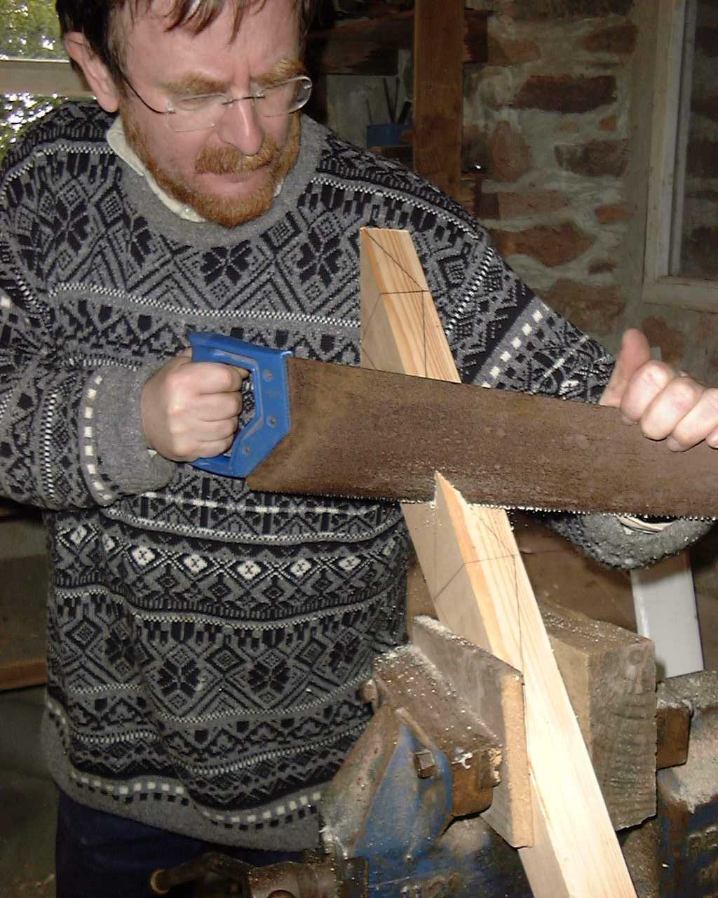
Pic 21: Here is a nice trick how to cut along 2 lines in 3 dimensions with
ease, somewhat of a mind twister when trying to visualize how you are going to saw this piece while drawing it up. A hand saw really does a great job.
( These are the blade wedges - Hugh)
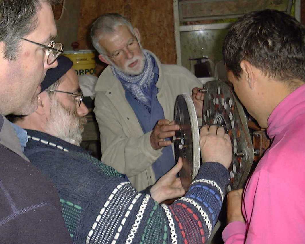
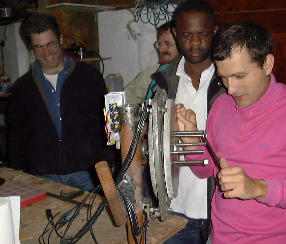
Pic 22: There was quite some tension in the air when the alternator was being assembled. Strong magnetic fields attract all the tools. The accuracy of all parts now pays off. (Here we see the front magnet rotor being fitted in front of the stator - Hugh)
Pic 23: The jacking screws work wonder. Actually, the attraction of the Neodymium magnets is so strong it would be impossible to control the assembly process without them.
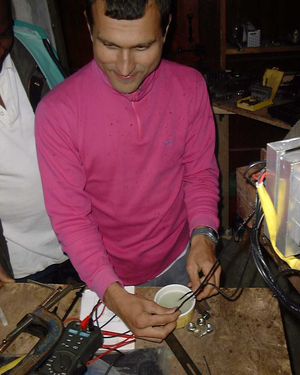
Pic 24: The diode voltage drop across the rectifier may be quite low, but even at 1 Volt and 5 to 10 Amps it starts dissipating quite some heat (5 - 10 Watts each).
(Twin heat sinks for the rectifiers. - Hugh)
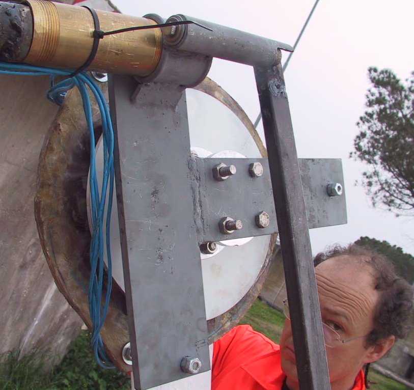
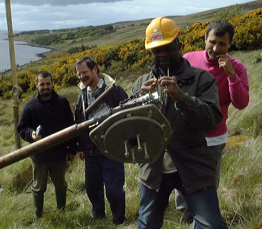
Pic 25: While Julius Tangka is trying to "rip off" the insulation, John and Stephan are checking the tail movement. We had to weld a small additional piece of steel to prevent the tail from hitting the hinge pipe weld.
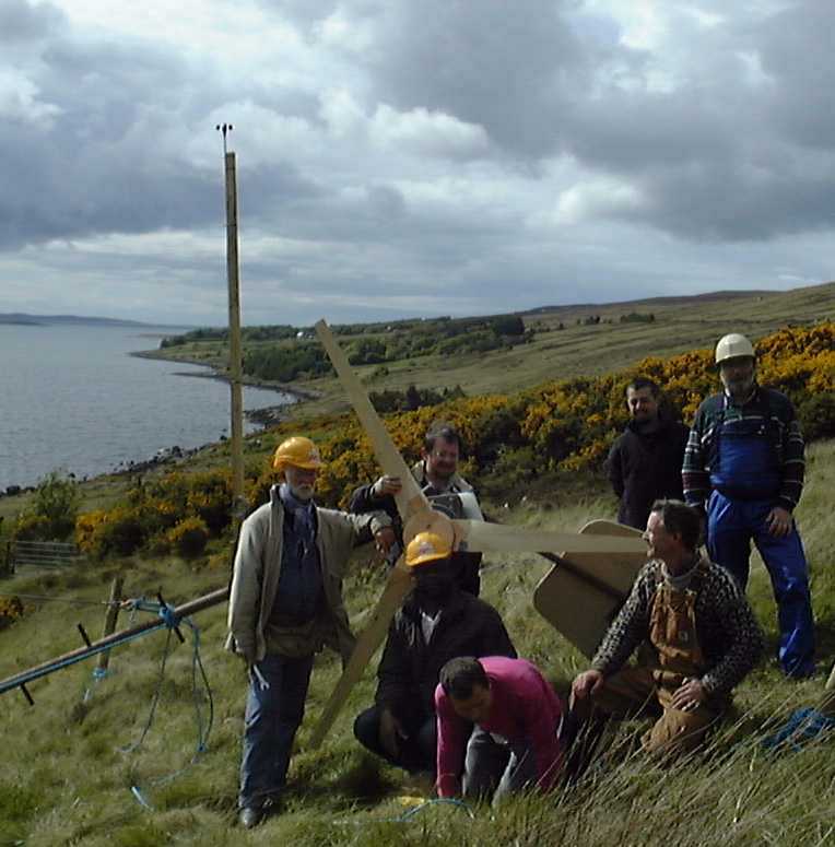
Pic 26: Lots of hands were needed to safely assemble the finished blades. It took some time to equalize the tip-to-tip distances while holding the centers together before we could clamp everything down and start drilling the mounting screw holes.
Pic 27: Can you smell the hydrogen?
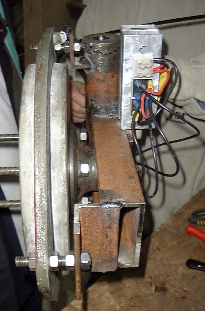
Pic 28: The completely assembled turbine in the workshop awaits static balancing.
Pic 29: Oops, a fuse blew. It is and was good advice to always use fuses with battery circuits, discharging currents can be huge. Julius Tangka flipped the polarity of the alternator wires and everything was OK then - after we used a new fuse.
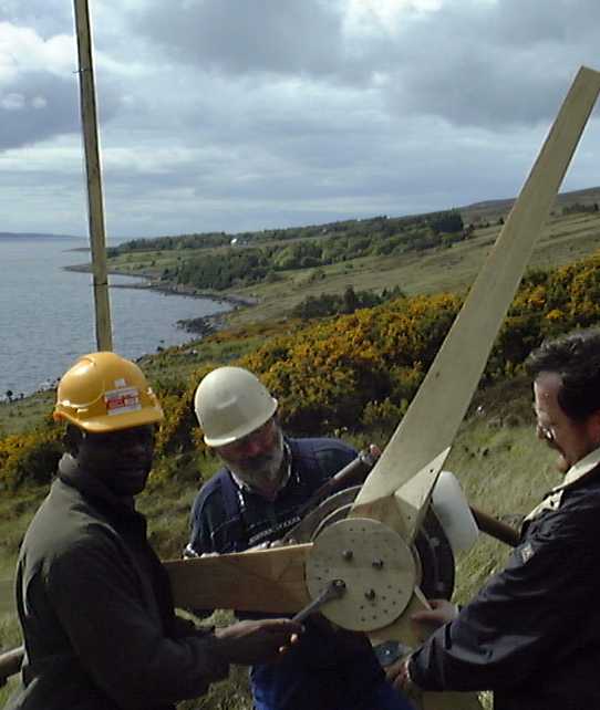
Pic 30: The last touch, tightening the blade assembly onto the alternator before raising the previously tested pole configuration, carefully of course.
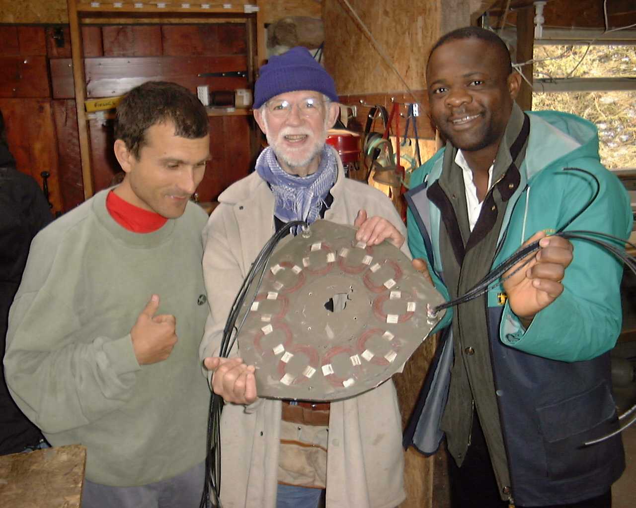
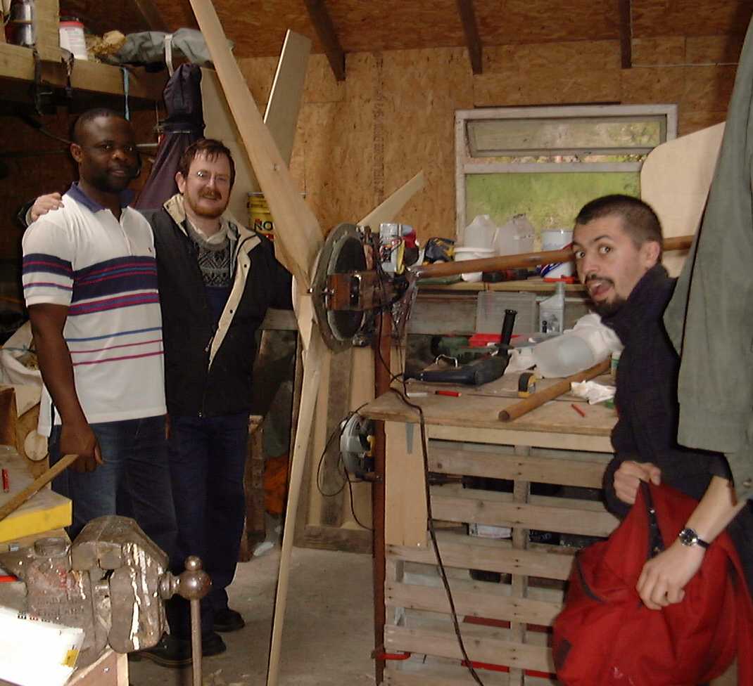
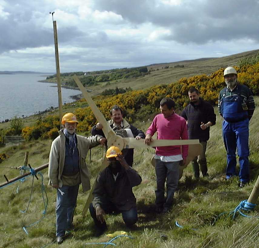
Pic 31: Here are some very happy and proud wind turbine scholars! Everything is in place, the anemometer reads 5-7 m/s winds, let's go.
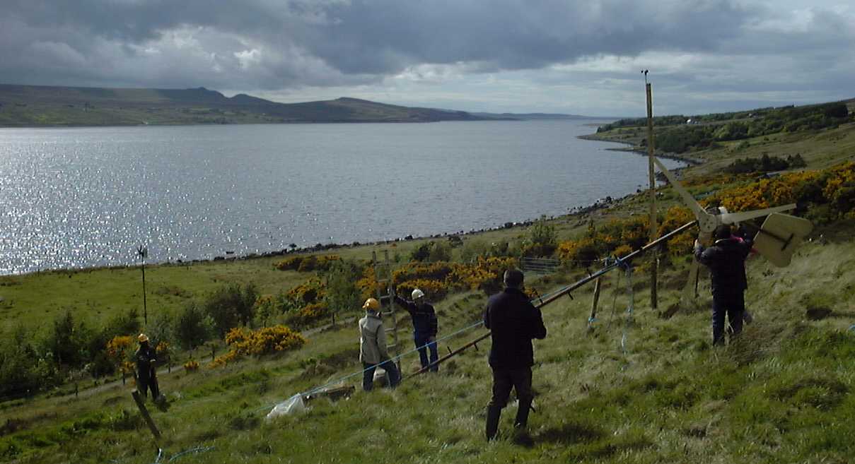
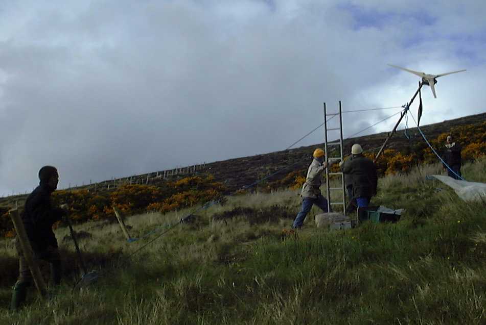
Pic 32: Julius Tangka is operating the winch while John and Uwe use the ladder to
guide the cable. Note that the tail is in full furling position. Some rain clouds
were approaching and we hoped to see some gusts, but....
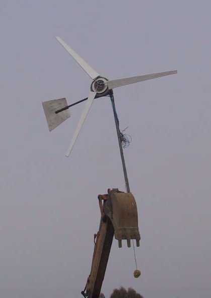
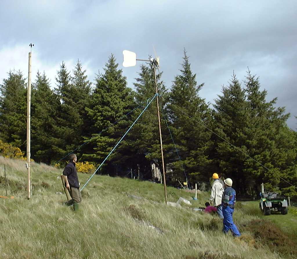
Pic 33: We were all looking - somewhat in awe - at the wind turbine we started building from scratch just 5 days ago actually generating electricity. What a rewarding moment! (We had an anemometer to check the windspeed. It was mostly around 3-5 m/s (7-11 mph)
Output was around 20-100 watts. Hugh)
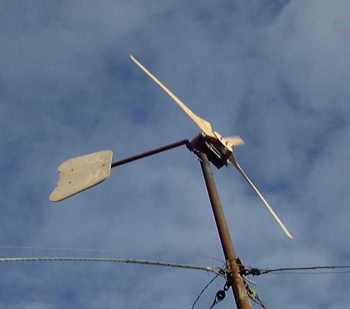
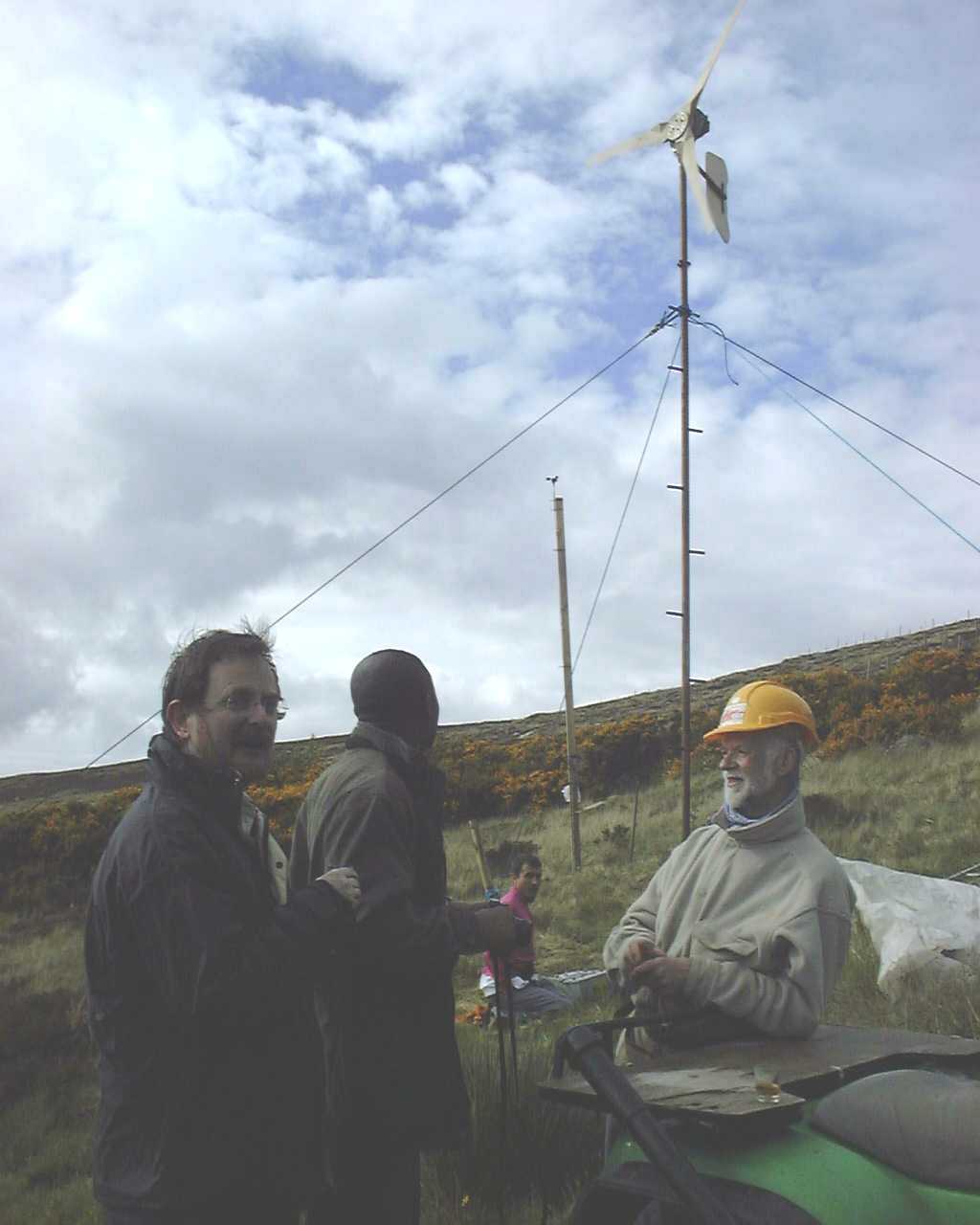
Pic 34: After the mill being up and running smoothly, no imbalance or
vibration could be noticed. The blade carvers must have done
a good job. Time to drink a toast! - Uwe
A few drops of very pure Scoraig rain water falling into our
drams released all the remaining flavors of an outstanding
single malt Brian offered. - Stephan
All too soon, it was time to take it down again....
All were happy to know that
Julius Tangka was going to arrange for transportation back
to Cameroon and that our wind turbine would help people
in their quest to teach and develop independent energy
projects.
The next course at Scoraig will be on 8-15th May 2004
"Thanks again for the wonderful course. It really
demystified wind turbine technology." Julius Tangka
"This course showed me what a small number of enthusiasts are
able to achieve." Uwe Hinz
There is a lot of exciting new stuff going on at the Otherpower discussion board where Dan is extending the design and using old Volvo parts to do it. Dan has put his latest wind machine project on this page.