There is also some supplementary information on my update page
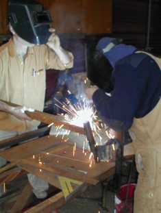
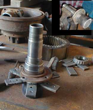
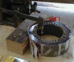
Below you can see parts for the brakedrum machines. The six tabs
welded to the axle tube are mounting lugs for the stator laminations.
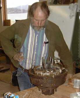
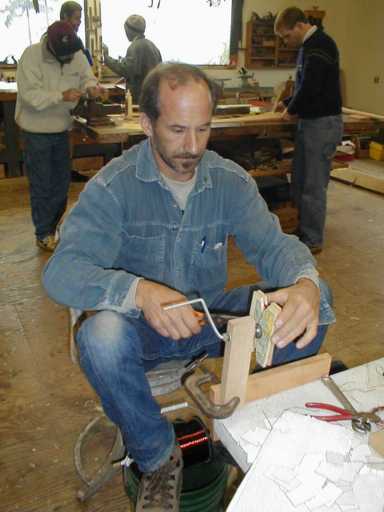
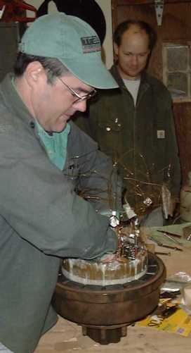
Here is Wally Stahle of Future
Electric Energy Co., San Luis Obispo CA winding coils for the stator.
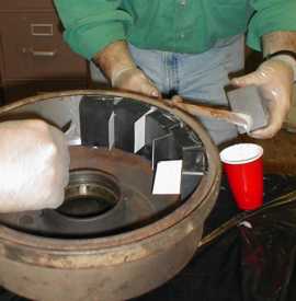
On the right is the special former used for clamping the coils. It
has a sheet metal liner to give a smooth surface of exactly the correct
radius. The cardboard in the photo is being used to simulate the
coils and create the correct radius while the liner is glued on.
I am grateful to Bob
Budd who taught me that trick and has an excellent video for sale,
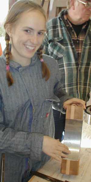
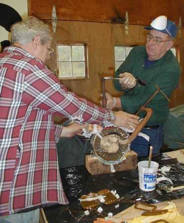
Here is Ian's daughter Rose Woofenden with the completed former, and
on the right you can see Ron helping Bob
Petersen of Kankakee IL clamping the coils down in epoxy. I think
Bob found my methods a little bit rough and ready compared to his own homebuilt
10kW machine, crafted with precision machine tools, but he did his
best to humour me.
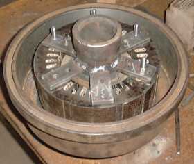
Below you can see the magnets going into the brakedrum. Dan Whitney
had the brakedrum skimmed out to fit the magnets in advance, and chose
material for the shims so that the magnets would fit neatly. The
magnets are 3x2x1" ferrite blocks from wondermagnet
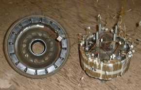
Below you can see the completed rotor and stator assemblies, and on
the right is Brian Faley assembling
them.
Below you can see the tail boom being welded to the brakedrum windmill
yaw tube. It is mounted on the side rather than the top, and we took
great care to angle the hinge correctly.
Dan Whitney (below) did not have the pleasure of seeing his machine
fly during the course but we were able to test the alternator and figure
out the best coil connection pattern for his application.