On this page:-
stator mounts
North american version coil dimensions.
finding bits
rectifiers
laminations
spreadsheet for design
another way to glue the coils on
tail furling system
how to know if an axle bearing is fully floating
or not
To clarify the differences between the solaced european and n american version of the design see this page
Magnet supplies - some links on this page. Magnets for the north american version (3x2x1" ferrite) are now available from wondermagnet.com for $5 each.
It has to be said that building a wind turbine is not like mowing the lawn, it is rather a challenge, and although my books will be an enormous help, they cannot make it into an exercise like assembling a kitchen unit from a flat pack. Not yet anyway. Maybe one day...
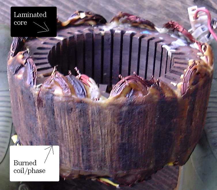
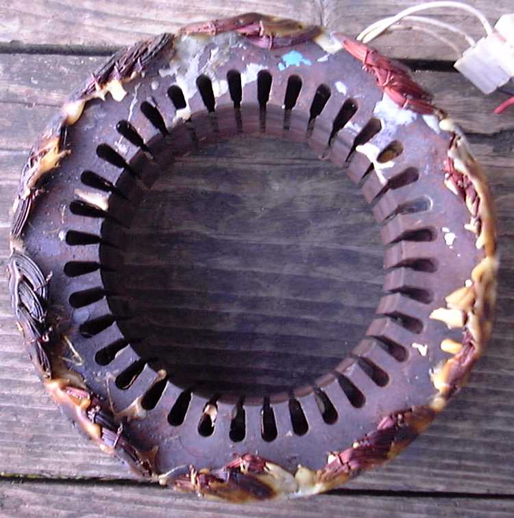
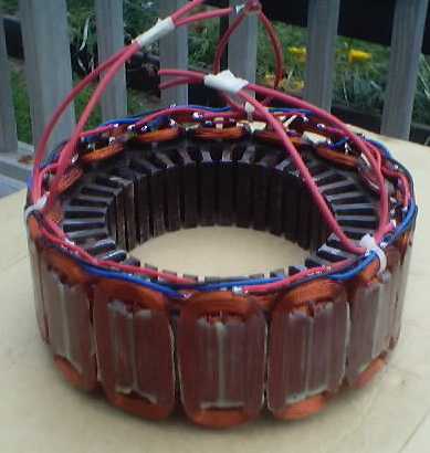
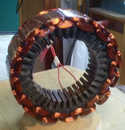
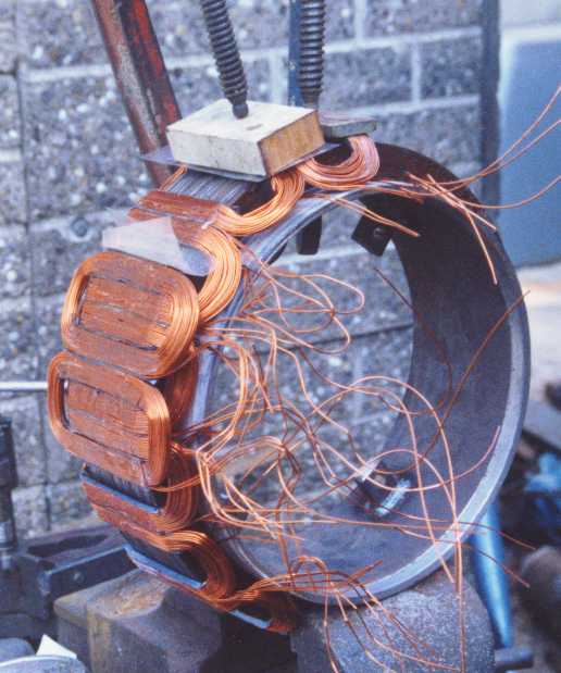
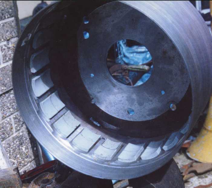
Problems seem to centre on the production of the stator. I have to agree that this is the hardest part to make. Here below are two pictures of the stator, for a start. It's an old one and has suffered some overloading on one phase due to a short circuit. This helps to pick out the shape of the phase which is burned - the middle coil in each heap.
As you can see, the air gap between the surface of the laminated core and the surface of the magnets is filled up with copper wires. This is how we extract the maximum power. At the ends (beyond the ends of the core), the coils overlap and are too thick to fit in the airgap - but this is not a problem because they are not in the air gap. The ends can be folded down hard if necessary, to make them fit the available space, but be careful not to damage the insulation.
A lot of people have recently started to ask how to get hold of
laminated
cores like this. Do not buy them as new or secondhand
items!
They are available for next to nothing as scrap
metal
from yards which specialise in dismantling and recycling old electrical
and other goods to sell off the metals. Here in the UK they are
called
scrap dealers or non-ferrous metal dealers.
There is much more about the laminations for the n american version
in an e-mail message below. Take care when
selecting
a stack of lams that you avoid or remove any
fastenings
or welds which might short circuit the laminations together near
or at the outer edge. These will cause high 'eddy currents' to
flow
which will waste power and slow the machine right down.
Before gluing the magnets into the brakedrum, first check that the stator will fit in the available space between the magnets. Some magnets can be placed within the drum 'loosely' for the purpose of this test. You want to have 1-2 millimetres (40-80 thousandths of an inch) all around the stator for a comfortable clearance. If the fit is too tight, then I suggest you skim the brakedrum inner bore on a lathe (or have this done in an automotive workshop - it is a normal job). This will give you more space to play with.
Here is an excerpt from an e-mail correspondence about how to mount the stator securely and centrally:-
>After purchasing and reading the subject book, I find that there is a >lack of information on how you mounted the stator (laminated core) to >the axle assembly. This seems to be an important procedure missing from >the "Putting it All Together" section of the book. Can you supply any >details on this? Happily. Last week I had a similar enquiry and was shocked to see how little help I give on the subject in the plans. Before that, no one had pointed it out, even though many successful alternators have been built. The plans have been on sale for seven years and I frequently update them to respond to comments such as yours. > Without these details, the subject book title is >misleading because incomplete plans are really not plans at all. They >become nothing more than a series of "ain't this cute" ideas. In reality is never possible to get the same component parts as I have used. Everyone has different sized parts from different sources. So it is essential to be flexible and find your own solutions for details. I assume this is what others have done. But now you point it out I can do much better by explaining it. Begin by measuring the size and spacing of the slots in the stator, which used to carry the coils. Find a size of bolt (or threaded rod) which fits snugly into the bottom of a slot. Place four such bolts through four slots. wedge the stator inside the drum, while the drum is on its bearings on the axle. Measure the size and shape of lug needed to hold the end of the each bolt. Bolts through the slots, into the holes in the lugs. Choose bolts (or long pieces of threaded rod) which fit snugly and carefully position the holes so that the bolts are in the bottoms of the slots. Centre the stator carefully and then weld the lugs in place on the back plate flange. The shape of the lugs and their position will depend on the shape of the brake system. If there is no flange in the right place to weld the lugs onto then make up tabs from strips of 1/4 inch steel flat bar.Drill holes at the outer end of each strip. Let me know if this is not clear :-)
From: "Andrew Purvis" <[email protected]>>
Date: Sun, 16 Mar 2003 08:24:06 -0700
Subject: [a-w-h] North American brake drum PMAI'm in the process of building Hugh Piggott's brake drum PMA.
I've got a couple of questions, and thought I'd share my
experience to this point.The rear axle was easily located at a self service wrecker. I
was fortunate, however, that someone else had already removed
the core (the internal gears) and the half shafts. This saved
me work, and reduced the cost. The wrecker has it down to a
science and has a separate price for the hubs, axle housing,
core and half shafts. Because it was self service, I did have
to have enough tools to remove the axle from the vehicle. The
resulting weight was about 175 pounds.I found a motor of about the right size on my first trip to
the local motor repair shop. It's a 20 hp motor, considerably
larger than the 5 hp required for the UK version, so I think I
got lucky. There probably aren't very many of those that get
tossed. The downside of such a large motor is that it weighed
150 pounds even after I removed the end plates and the rotor.
The laminations turned out to be 9 1/2 inches instead of the 9
5/8 called for in the plans, but I think I'll make do.To split off the case of the motor I put a metal cutoff blade
on my circular saw. This had the advantage of allowing me to
control the depth of cut fairly accurately, so there was
almost no damage to the laminations. I actually didn't quite
cut all the way through, and used chisels to pry apart the
case enough for it to break at the cut. I had to make another
cut on the opposite side to get the case to break in half. I
discovered that the second cut should be EXACTLY half way
around, or the laminations have to be pried out of the
slightly larger half.Now to the questions. I'm just about ready to test fit the
magnets into the drum. After a comment from Hugh that I saw
in the archives, I started to wonder if the magnets would
actually all fit. Based on my calculations, it's going to be
close, but probably leave no gap. How important is the 1 mm
gap between magnets? I've seen some mention of flux leakage
directly from one magnet to the other, but I'm wondering how
significant this will be. The less shaping of the magnets
that I have to do, the better. Turning the drum slightly
larger won't be an option because the laminations are already
on the small side.The second question has to do with the air gap. It looks like
I'm going to have a gap of about 4.5 mm. How badly will this
affect the performance of the machine?Thanks for any comments.
Andrew
Yes I think that is a better size actually. Bob's sizes are a
bit tight.
>
>
>Now to the questions. I'm just about ready to test fit the
>magnets into the drum. After a comment from Hugh that I saw
>in the archives, I started to wonder if the magnets would
>actually all fit. Based on my calculations, it's going to be
>close, but probably leave no gap. How important is the 1 mm
>gap between magnets?
the magnets can touch each other if you like. That's
fine.
They
have quite high reluctance anyway, so there will not be much increase
in leakage this way. I like to fill the space with magnets if
I am
using ferrites.
>I've seen some mention of flux leakage
>directly from one magnet to the other, but I'm wondering how
>significant this will be.
Very significant. But in this case you have limited space for
magnets so you might as well jam them in. You will get better
flux
this way than with smaller magnets.
>The less shaping of the magnets
>that I have to do, the better. Turning the drum slightly
>larger won't be an option because the laminations are already
>on the small side.
You could use a thicker winding. That would be OK. A
larger
gap
between magnets and lams is not a problem. You gain on copper
and
lose slightly on flux density so overall it is no big deal.
>
>The second question has to do with the air gap. It looks like
>I'm going to have a gap of about 4.5 mm. How badly will this
>affect the performance of the machine?
That sounds quite small to me now. You might make it
bigger.
Fill
it with copper but keep a sensible amount of mechanical gap.
I'd
suggest making the stator first and then deciding whether to skim
the drum larger. Aim for a 1.5mm clearance between coils and
magnets.
From: "Andrew Purvis" <[email protected]>
Date: Thu, 20 Mar 2003 13:59:51 -0700
Subject: Re: [a-w-h] North American brake drum PMAOn 20 Mar 2003 at 8:04, Ron Dinishak wrote:
But its easy for a first time builder to miss that and
more importantly the coil former listed on page
18,third column of Y2K is too small. The legs of the
coils have to be longer than the laminations or else
the ends of the coils will over lap in the airgap and
the stator won't fit. I used something like
410mm(4.5") for my leg length. (The second time I
wound the stator.) :)-------------
Thanks for pointing out the coil former problem. I hadn't
noticed the the leg length for the UK version was bigger the
the lamination thickness. Duly noted in the plans now.I've decided to increase the coil thickness to 4.5 mm. This
will hopefully allow me to put in a double coil of 0.8 mm wire
(that I painfully recovered from the recycled motor itself)
reducing the resistance to half. By double coil, I mean
simultaneously winding 2 sets of wire in parallel and joining
the ends, giving the equivalent of about 1.1 mm wire (based on
cross-sectional area). My calculations say that the coil will
still be less than 10 mm thick in the other dimension. I've
yet to do a test coil to see how much the real world is going
to interfere.Keeping the mechanical air gap at 1.5 mm gives a total air gap
of 6 mm. My drums are well worn, so minimal turning (mostly
taking off the ridge on either side of where the shoe
contacted) will give me a enough room for the magnets and even
a bit of space between then (especially since I've already
hand ground off about 0.5 mm of each inside corner - magnetic
filing are a real pain). It also helped that the nominally
1X2X3 magnets from Magnetsource were actually 25X50X75 mm.Andrew
At 2:04 pm -0800 8/2/01, Bruce Gebbeken wrote:
I purchased from R.A.M. some time ago the 1999 edition
of "The Brakedrum Windmill" original design by Hugh
Piggott. Those folks included Hugh's Mathematical
Model of the Brakedrum Alternator on the back page.the spreadsheet is also available on their technical page at
http://www.ramdesign.on.ca/windmill/tech_.htmNow I have some questions on the formulas that I hope
someone could help this old goat out on, if it is not
too much trouble;Feedback is always welcome, so I can improve what's on offer.
1). Total power generated, in watts, your basic I*R.
mistake. I*R is volt drop. V*I is power.
The formula shows P = VBAT * I, shouldn't this be P =
VALT * I ?No. VBAT is the actual voltage when the battery is connected. VALT is the 'open circuit voltage' which you only see when disconnected.
2). The determination on wire diameter, in mm. Does
this formula work outside of the brakedrum alternator,NO see, my 'assumptions':
1. I assume that the stator winding is 2.5mm thick, in a total gap of around 4mm.
This determines the available space for the wire, and hence the wire size you can use.and what does "0.7" and "0.5" represent anyway? Are
they constants?yes. DWIRE = 0.7*(W/T)^0.5
All these formulae are rules of thumb using constants. 0.7 is a constant which works for this situation. (W/T)^0.5 is computer-speak for 'square root of' W/T.
3). Hugh assumes that the alternator is wound Star.
How are the formulas affected when winding Delta?if the coils are re-connect delta then the output voltage VALT will be reduced by a factor of 0.58 (=1/root3). Internal resistance R is reduced by a factor of 1/3.
VALT =N^2*L*W*T*RPM/260000000
R =(L+W)*N*T^2/W/26000
But star connection is marginally more efficient.
4). Are the alternator formulas affected by the type
of magnets used?Yes this assumes the use of ferrite magnets. The magnets need to be 20-25mm thick, and at least 32 mm wide.
My basic electronic theory says yes,
however I am getting older and duller. What formula
correction would be used for, say, Ceramic vs.
Neodymium?My researches have not reached the point where I can make a confident statement about that. Neos ought to give about 3 times the flux, but there are many factors.
5). When using these formulas to modify the
alternator, at what speed formula-wise should I
consider physically cutting out the alternator to keep
from melting it into a blob at the base of the tower?
This of course means electrically.You need to look at the internal LOSS =I^2*RI and consider whether the temperature rise will be excessive. The answer will depend on how well cooled the stator is. There is no accurate formula which can tell you that a particular size of wire can carry a particular current in a winding.
If you keep the power output down, then the alternator will last for ever. If you thrash it, then the windings will fall off the laminations after a few years.
6). Now allow this old man one last question. Without
going out to buy a Rosenberg ($90), or re-purchasing
the more complete "Direct from Hugh Version" of the
Brakedrum Alternator with the enclosed formuli, is
there a place to download updated versions of these
and other alternator formulas? They seem to be no
longer on the PicoTurbine web site as mentioned in my
book.I am always <mailto:[email protected]>here to answer questions, and I endeavour to improve the design where I can. I have started a page a http://www.scoraigwind.co.uk/brakeupdate where I try to put helpful stuff. This message may well find its way onto that page later.
I did this design almost eight years ago now and of course I have had plenty of brand new ideas since then. The old brakedrum idea is not the be-all and end-all for me, by any means.
--
HughScoraig, Scotland
http://www.scoraigwind.co.uk
At 5:41 am -0800 19/2/01, James L. Jacobs wrote:
>After buying Hugh Piggott's "Brakedrum Windmill Plans" a week ago
I
>decided to visit the local pull-it-yourself auto junkyard to check
>availability and price of the Ford 3/4 ton rear end. I was
dismayed
at
>the price: Ecology recycling in San Diego, Calif. wants $175 !
You could get a lower price if the differential gearbox is beyond repair.
> The shape
>on these brakedrum varies significantly from the drawings; the hub
>containing the bearing extends ~4 inches out from the flat area on
the
>drum where the wheel lug nuts are located. This feature will make
it
>difficult to attach the prop assembly.
It is possible to use either of two 'fixes' for this problem.
Either
bolt the rotor direct onto the end of the bearing hub, or build it
around the hub. Both of these have been done successfully.
If the
rotor is very large then it may not sit comfortably on the end of the
hub and a piece of steel plate can be used to extend the bearing
surface into a larger flange.
>
> But I did not give up.
That's what it's all about. Real life throws up challenges
like
this. For fuller details of the north american version of the
alternator, contact Robert Budd in Ontario http://www.windmill.on.ca
> I noticed that while most vehicles had front disc
>brakes there were still a few with front drum brakes. Some of the
drums
>were quite large and would seem to be appropiate for the task. The
price
>of drum+spindle is $54....certainly easier to remove and more
affordable.
>
>Has anyone used one of the front drum/spindles to build the
alternator?
I see no reason why a front hub should not be suitable so long as
the
brakedrum is deep. It's hard to find them though.
--
Hugh
Lams are often a problem, it seems. I have never built one of
the
North American version yet. Robert Budd is the man. The
magnets for
this version are now available from wondermagnet.com
I found out recently that the north american version has a problem
with inadequate space for magnets if the drum is exactly 12 inch
internal diameter. The drum actually needs to be skimmed out
on a
lathe to accept 16 magnets if they are really full 2 inches wide
(50mm is OK). Skimming out brake-drums is a very standard
operation
which should not cost much to do (and may have already been done if
you have an old one).
> The local scrap
>dealer and two rewind shops have been very enthusiastic and have
>actually volunteered to pile up motor cores for my return visit. As
>soon as you tell them you're attempting to build a motor out of a
>brake drum, they seem to become interested and helpful.
fun, isn't it :-)
>
>I want to point out that I have only looked at about twenty-five 3
>phase motors so far, so it's not that I can say I'm having a
>hard
>time finding the proper laminations. But I really am curious to
know
>how others are making out? I also saved this 9 ? inch set of lams
>just in case I don't find the 9 ? inch set.
Ideally you want 9.5/8 or even 9.3/4 inch lam diameter for
that.
A
smaller lam gives you more room for maneouvre with the airgap though
and even more room for a heavier winding if you want to. There
is
some loss from having too small lams but you can still get a result.
9.1/4 seems very small. One idea to improve that would be to
glue
steel pole pieces onto the magnet faces, which would narrow the gap.
Or you can take a 10 inch lam and skim it down. Try not to short
circuit the lams to each other.
I have put some useful extra ideas about the brakedrum building
process on http://www.scoraigwind.co.uk/brakeupdate
>
>After spending some time reading various threads, I see that there
>are a few individuals that have mentioned making their own
>laminations. This has caused me to think of ways to produce
such a
>thing in small numbers. The other day, I visited a good
friend
who
>specializes in water jet cutting. He explained that cutting a stack
>of laminations would be no problem for a water jet cutting machine.
>If you are not familiar with this technology, small garnets are
>injected into the water stream and do the actual cutting.
>
>There are several potential benefits to this method of forming
>laminations, small batches are possible, and Unlike a punch die,
you
>can change the CNC program to improve your design if necessary.
>Since the cutting is done under water, there is no heat distortion.
>As I see it, the water cut laminate might even look better than a
>part off a punch press?
sounds good but how much does it cost??
>
>If moderate amounts of laminations were to be created, a large
stack
>of sheet metal could be inserted in the tank, and the CNC program
>could cookie cut rows and columns of same.
>
>Hmmm, I wonder how much interest there would be in a set of custom
>laminations for the brake drum machines?
Incidentally there are a couple of things to watch out for when
using
old lams. Beware of rivets near the edge which can short circuit
the
lams and create eddy currents. They act like coils but the
current
flow within the lams and not the copper. Remove any such rivets
or
straps, and clamp the lams using bolts through the slots. Another
thing to watch for is slots or flats on the circumference. Fill
these with resin loaded with iron filings to get the best results.
I am always here to offer help where I can.
--
Hugh
Scoraig, in Scotland.
http://www.scoraigwind.co.uk
========================
At 02:21 PM 5/11/02 -0700, Daniel Day wrote:
>Hello all,
>
>First of all, many thanks to Hugh, John, Randy, Joseph and
>Larry for their answers on- and off-list to my question last
>weekend.
>
>I fot a scrapped motor and cut open the case in order to get
>out the core. In cutting open the case, I messed up big
>time: not realizing the core is just inside the case, I cut
>into the core, and thus the laminations are now shorted to
>each other by the cutting slag. Thus, question 1: Can this
>core be saved?
>Assuming it can be saved by (I assume) just detaching the
>laminations from each other, filing off the slag and
>re-stacking the laminations, I would also like to ask the
>best solvent for removing the motor windings from the inside
>of the core.
>
>The core is about 10-1/4" in diameter. It looks like a brake
>drum with a 12" ID will be about the right size.
>
>Dan Day
>Corbett, OR
Dan,
I don't think you need to worry about what you have done to the core.
There
is always some electrical connection between the laminates in a core.
Just
file or grind off the slag.
As for a slovent for removing the windings, I suggest elbow grease.:)
What
I do is use a band saw to cut thru the copper near the laminates on
one
side and then pry the turns out the other side with a screw driver
or some
other prying device.
Jim Hannon
=================
Hi Dan,
Just a my two cents here.
You only really have to remove the outside welds that
hold the lams together. It was strange when I first
saw them too but, thats how the big motor lams are
held together. That's why the lams are "shorted." It
is not the power loss that's a big deal. The problem
is when you glue your coils over those welds, the
welds will act like shorted coils and make heat and
melt the glue. Just grind them out and don't worry
about it.
This part is NOT recommended but included for those
that want to take the lams apart;
{
I took my lams apart and cut them down with tin snips
so it would fit. It wasn't half as bad as it sounds.
Came out pretty good and round. The problem I had was
when I tried to glue it all back together. The wet
epoxy is like oil, slipping and sliding around. Then
when I finally got it where I could clamp it, I
couldn't clamp it perfectly flat. It has little
vallies where the clamps were and hills where they
weren't. Next time I'll glue about 6mm(1/4") at a time
and glue those pieces together. Bottom line: Don't
take it apart, Unless you just can't resist. I wanted
to pratice so I could try to make a stator with slots
and compare the performance difference.
}
Another thing I found out was: You don't have to glue
the magnets in right away. You can wait until you've
completed the stator. Just in case you need some more
clearence. Grinding the magnets should be avoided but,
it is much, much easier to do with out them glued in!
Plus in case you change your mind, after hand testing,
you can get your magnets back.
Thanks RonD
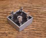
Hi ,Ooops. Nobody has pointed that out before that I can rememberI just got the Brakedrum Windmill Plans ...........That is what I was writing about .. The rectifiers spoken of on page 17 and are not in the list of parts...
Are all rectifiers the same ....can you put any rectifiers any size any voltage on this windmill?The rectifier(s) have to be able to handle the full output current. I normally use 2 'single phase' rectifiers. If you expect (say) 20 amps output then you would want at least 15 amps rating on the rectifiers but they are cheap so it is worth over-rating them. You can parallel them to get more current if you cannot find a high enough current rating. Voltage ratings usually start at about 100 volts and this is sufficient.
The Plans do not say or explain how it is hooked up .Last paragraph on page 17 says .connect the + side of the battery to one side "of the rectifier?" and connect the -of the same battery (to the other side of the rectifier?"There is a diagram on page 18 which I thought was quite clear.
.............yes I guess the rectifier would get hot. This is not real clear , is that correct, I am trying how about a little help before I buy another set of plans.It does get warm. It is normal practice to put it on a heatsink to prevent overheating which would occur if it was not cooled in any way.
This is what they usually look like-
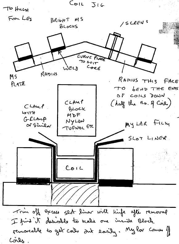
Thomas moar wrote:
My coil winding jig is similar to the one shown in " The Homebuilt
Dynamo"
except that I used Aluminum alloy for the side plates. I found that
a few
drops of unthickened resin applied to the windings would find its way
completely round the coil thus giving a rigid coil after the resin
has
cured,also it does not adhere to the alloy when fully cured. I made
up a jig
to bend the ends of the first 15 coils over, I used UHMW plastic for
this to
avoid damaging the enamel. After clamping this in my bench vise I
tapped
the
ends over using a block of UHMW and a hammer.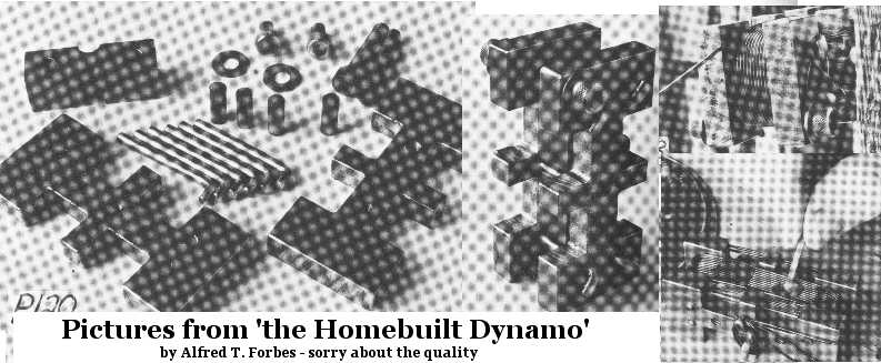
"The Neodymium magnets I used are 46mm x 30mm x 10mm. I got them from MAGNA Co. Ltd. JAPAN. I paid $100. Thier Email address is. [email protected]"
From: "thomas moar" <[email protected]>
To: "hugh piggott" [email protected]
Subject: Re: Neo alternator tests
Date: Sat, 10 Nov 2001 13:38:07 +1300
Thanks Hugh,
I happened to have a 1000watt Radiator rod, This is a round ceramic rod
overwound with resistance wire.
After connecting this to the DC output I got the following results.
At 55rpm = 26v DC. 157rpm = 75v DC. 172rpm = 81v DC. 212rpm = 97v DC.
282rpm = 132v DC. 471rpm = 214v DC. At this point the Radiator rod is red
hot so I guess that I have pretty close to 1000watts.
With my test set up I am able to put my finger on the coils of the
alternator, after a few minutes I can feel no heating, Maybe I should let it
run longer? Thomas.
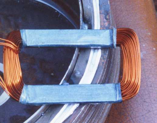
Les writes: "The blue stuff round the coil is a cheap slot
liner material, elephantide with a polyester layer bonded on. I just
have
lots of it. The ideal material would be un callendared nomex but
could be difficult to get in small quantities. Ordinary Nomex would do,
from R.S. but is stiff to work.
The elephantide is only a class E ( 120 degree ) insulation, but I
used the SP wood glue that you use and I have no idea of it's
temperature
limits. I wouldn't trust it above 100 degrees.
"I wind the coils on a simple split former as you do. I then clamp
them
in another former and set them in resin. The slot liner material
acts as
the release agent and provides the insulation from the core and also
interphase."
This is Michael O'Brien in Australia.
Hi. Is it OK to put your message and my replies onto my web page http://www.scoraigwind.co.uk/brakeupdate ?
I recently purchased your book, Brakedrum Windmill Plans and have
been
reading
it with interest. Thank you for writing it and making it available.
It was a pleasure.
If it's okay, I'd like to ask you a few questions please...
1. How did you attach the laminated core inside the brakedrum?
(Unless I missed it, it doesn't seem to be covered
in your book.)
check the web page above for more detail. I
agree it is poorly covered.
2. You made your design to be most efficient in low winds, but
your book
talks about your site being so windy that other
wind turbines have
failed. This is a bit confusing. What is the normal
wind speed in your
area?
Average windspeed is about 6m/s (13mph). We get some very high winds, but at those times the batteries are usually full. What matters to me is to get good power output in low winds so that the power supply is more consistent. And to survive the gales. In high winds it is easy to get plenty of power at low efficiency, but in low winds there is very little to be had so that is when the machine needs to be very efficient.3. How can I relate the RPM to the wind speed?
The rotor tip speed ratio is designed to be around 6, I think. But at cut-in it will be unloaded and therefore run at a higher speed say 7.5. To work out the windspeed at which it can do 200 rpm, first work out the tip speed at 200 rpm and then divide by 7.5 (or so).Tip speed is 200/60 revs per sec x 2.1 x 3.14 metres per rev = 22m/sec
cut in speed will therefor be about 22/7.5 = 3 metres per second wind.
Finally, and this may be the most difficult to answer... I'm also
trying to
design and build an alternative style wind turbine: One with vertical
wings
rotating around a vertical axis. From what I've read, this will rotate
faster
than other types - with the potential to produce more power from the
same
amount of wind.
there is a lot written about vertical axis but they are not so successful in reality. There are serious fatigue problems and the performance is not that great. I do not recommend this approach.Once I have tested the design to determine its normal rpm for our wind
Thank you very much for your help.
a bigger one will give more power at lower speed.
Kind regards,
Michael O'Brien
(Tasmania, Australia)
you are welcome.
At 11:38 pm +0200 7/4/02, ilcarrascosa wrote:
Thanks for your answer,Mr Piggott.
Anyway, I understand yet the movement and the angles of the tail vane and boom (15º to allow the vane go up in a cone-way, and 45º to allow the vane to turn 90º). But I still not understand how the lift and the weight could be balanced. I mean that the tail-vane weight is a vertical force, and the lift and the thrust are horizontal, doesn´t they?
If you have a cart on a ramp you can use a horizontal force to push it up the ramp. It moves vertically. The weight of the cart will oppose the movement. When you stop pushing, the cart will run down, and move you horizontally if it has to.
From: "ilcarrascosa"
<[email protected]>
To: [email protected]
Subject: Thanks
Hello again Mr Piggott.
I decided to draw the machanism on 3D to understand on the space the movement of the tail-vane, and finally I've seen right that the the relative turning around the axis wich conects the boom and the rotor is the main reason (this 15º). When I saw on your book I couldn't imagine exactly how could the tail-vane get upwards, but once drawed and gived movement to the mechanism I've understand.
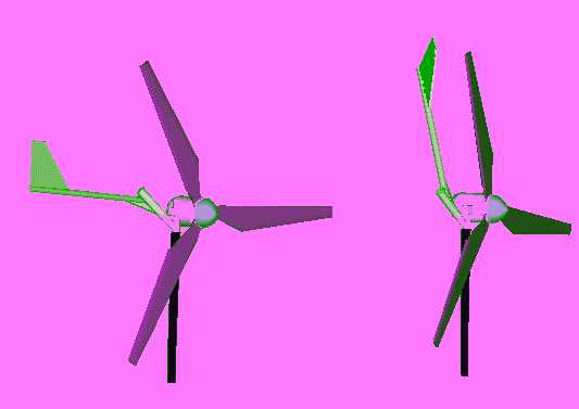
I send you two drawings of the mechanism. This
is only a basic scheme, and the tail, tower and nacelle dimensions are
not the right ones (now I'm going to start with the calculations of the
real dimensions, and also thinking on re-designing the furling
mechanism).
It goes without saying that if anytime you need help with drawings or something else, please tell me and I will be very proud to help you.
Best regards, Mr Piggott.
NOTE: The vane on the above windmill seems to be at a funny
angle
- I would expect it to appear to the left of the boom, in the
right
hand drawing above. - HUGH
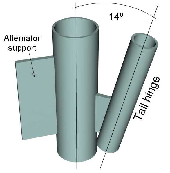
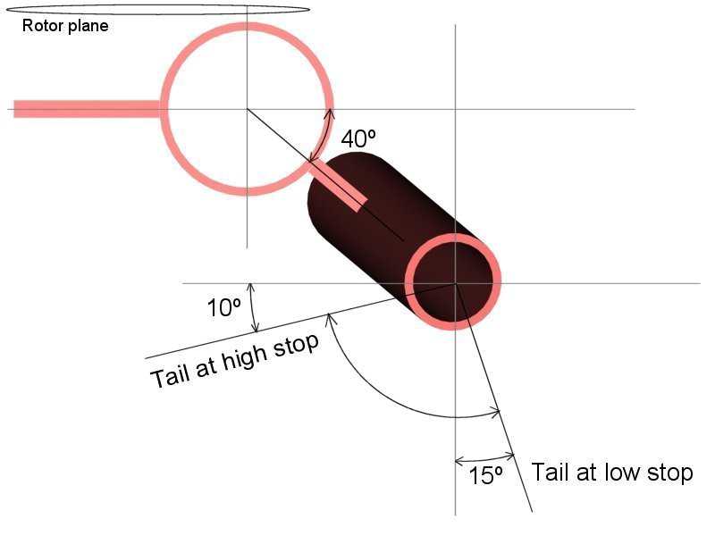
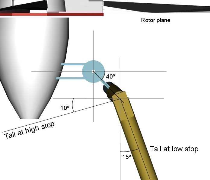
"José
Galán"
<[email protected]> or 'pepe' has also made some nice
drawings
of the tail furling system (see below). Note that the angle is
different
from the ones published in the plans. This will work just the
same,
but you need a heavier tail. I now prefer hinge angles about 18
degrees.
The angle in these drawings is 14 degrees off vertical.
From: "josephturrisi"
<[email protected]>
Mailing-List: list [email protected]; contact
[email protected]
Date: Sun, 05 May 2002 03:25:49 -0000
Subject: [a-w-h] Re: Axle bearings in brake drum
The best way to find out if the bearings are full floating is to
look
at the axle. If it is a full floating design you will be able to
remove the axle from the rear end housing without taking the wheel
off. The most common axle of this design in the USA is the Dana 60.
It
can be found in most 1 ton pickups and some 3/4 ton pickups. Again
you
will be able to remove the axle shaft from the housing without having
to take off the wheel. These axles also have a 8 lug bolt pattern that
holds the wheel/tire on.
--- In awea-wind-home@y..., Daniel Day <gamshara@T...> wrote:
> Hello all,
> I have a question for Hugh Piggott and the mechanics in the
> list about Hugh's specification of the type of support
> between the drum and axle in his brakedrum windmill plans:
>
> 'You need "fully floating" bearings on the hub, i.e. the hub
> must be supported by two bearing races, even after the half
> shaft is removed.'
>
> Is there a way to find out if the bearings are fully
> floating aside from cold-calling auto mechanics (I hate to
> be a pest) or looking the truck model up in auto-repair
> books in the library (I did, but no books had this
> information)? Also, if the brake drum is large and
> bell-shaped, rather than cylindrical, and is mounted on a
> pickup truck, can we assume that the bearings are this type?
>
> I found a large brake drum on a Chevy Scottsdale at a local
> junkyard. The OD was over 14" and the length of the exterior
> at the largest-diameter portion of the drum, corresponding
> to the section where the brake pads are applied inside the
> drum, was about 4". As long as the bearings are the right
> configuration, this drum looks like a good prospect.
>
> Can anyone give any pointers here? Thanks much in advance.
>
> Dan Day
> Corbett, Oregon